This thread has been locked.

If you have a related question, please click the "Ask a related question" button in the top right corner. The newly created question will be automatically linked to this question.

TM4C129XNCZAD: I2C Master TRANSMIT of Multiple Data Bytes Issue

Part Number: TM4C129XNCZAD

Hi,

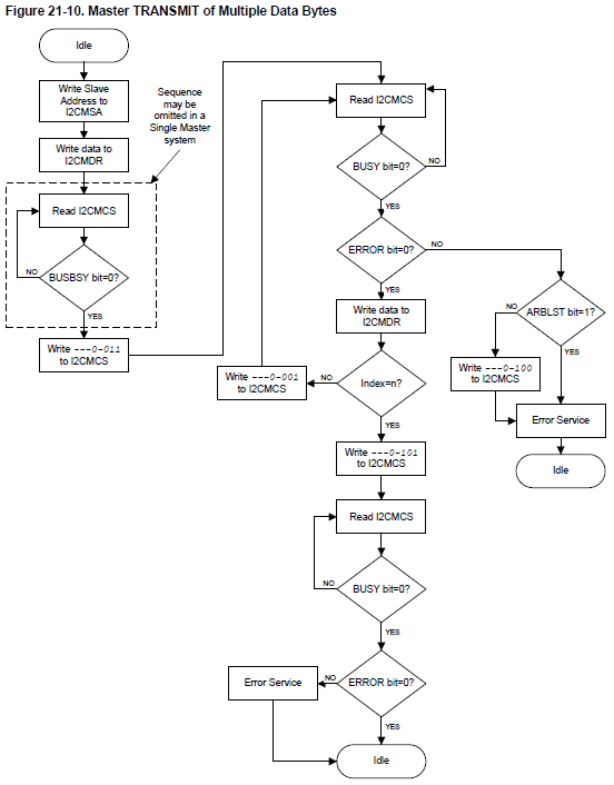
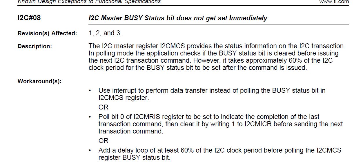
I am trying to follow the flowchart given in the datasheet to transmit 4 bytes out from I2C. However, I can only manage to see 0x34 and 0x78 being transmitted out from the scope while the other 2 bytes lost in the air. Below is the code and flowchart for reference. Need a second pairs of eyes to see what I have missed in my code. Thanks.

My code:

int main(void)
{

//Enable clock to I2C and GPIO Port A
*((uint32_t *)(SYSCTL_RCGCI2C)) |= (0x01 << 9);
*((uint32_t *)(SYSCTL_RCGCGPIO)) |= (0x00001 << 0);

//Wait for the SSI Interface and GPIO Port A Peripheral to be ready
while(!(*(uint32_t *)(SYSCTL_PRI2C) & (0x001 << 9)));
while(!(*(uint32_t *)(SYSCTL_PRGPIO) & (0x00001 << 0)));

//Configure the GPIO alternate function as I2C
*((uint32_t *)(GPIO_PORTA_AHB + GPIO_O_AFSEL)) |= (0x03 << 0);
*((uint32_t *)(GPIO_PORTA_AHB + GPIO_O_ODR)) |= (0x01 << 1);
*((uint32_t *)(GPIO_PORTA_AHB + GPIO_O_PCTL)) = (0x2 << 4 | 0x2 << 0);
*((uint32_t *)(GPIO_PORTA_AHB + GPIO_O_DEN)) |= (0x03 << 0);

//Configure the clock source to use PIOSC
*((uint32_t *)(SYSCTL_PLLFREQ0)) |= (0x1 << 23);
while(!(*(uint32_t *)(SYSCTL_PLLSTAT)));
*((uint32_t *)(SYSCTL_PLLFREQ0)) &= ~(0x1 << 23);

//Configure I2C as master mode
*((uint32_t *)(I2C9 + I2C_O_MCR)) |= (0x1 << 4);

//Configure SCL clock speed to 100kHz
*((uint32_t *)(I2C9 + I2C_O_MTPR)) = 0x08;

//Configure the slave address and operate in transmit mode
*((uint32_t *)(I2C9 + I2C_O_MSA)) = (0x76 << 1 | 0x0 << 0);

//Wait until the bus is idle
while((*(uint32_t *)(I2C9 + I2C_O_MCS)) & 0x00000001);
while((*(uint32_t *)(I2C9 + I2C_O_MCS)) & 0x00000040);

//Transmit 1 byte of data
*((uint32_t *)(I2C9 + I2C_O_MDR)) = 0x12;

//Initiate 1 byte transmission
*((uint32_t *)(I2C9 + I2C_O_MCS)) = 0x03;

//Wait until the I2C is idle and no error
while((*(uint32_t *)(I2C9 + I2C_O_MCS)) & 0x00000001);
while((*(uint32_t *)(I2C9 + I2C_O_MCS)) & 0x00000002);

//Transmit 1 byte of data
*((uint32_t *)(I2C9 + I2C_O_MDR)) = 0x34;

//Initiate 1 byte transmission
*((uint32_t *)(I2C9 + I2C_O_MCS)) = 0x01;

//Wait until the I2C is idle and no error
while((*(uint32_t *)(I2C9 + I2C_O_MCS)) & 0x00000001);
while((*(uint32_t *)(I2C9 + I2C_O_MCS)) & 0x00000002);

//Transmit 1 byte of data
*((uint32_t *)(I2C9 + I2C_O_MDR)) = 0x56;

//Initiate 1 byte transmission
*((uint32_t *)(I2C9 + I2C_O_MCS)) = 0x01;

//Wait until the I2C is idle and no error
while((*(uint32_t *)(I2C9 + I2C_O_MCS)) & 0x00000001);
while((*(uint32_t *)(I2C9 + I2C_O_MCS)) & 0x00000002);

//Transmit 1 byte of data
*((uint32_t *)(I2C9 + I2C_O_MDR)) = 0x78;

//Initiate 1 byte transmission
*((uint32_t *)(I2C9 + I2C_O_MCS)) = 0x05;

//Wait until the I2C is idle and no error
while((*(uint32_t *)(I2C9 + I2C_O_MCS)) & 0x00000001);
while((*(uint32_t *)(I2C9 + I2C_O_MCS)) & 0x00000002);

while(1);
}

  • May I note that your posting reveals much care & skill - yet is "outside the preference"  of (most) vendor agents - and we outsider (sometimes) helpers.    This proves so due to your exclusive use of the "Direct Register Manipulation" (DRM) code style - which demands that the MCU Manual be, "At the Ready" -  introducing much complexity - while raising (both) the "time & effort" burden - forced upon your helpers.

    Use of the vendors "API" is (very) much preferred - especially as it is well noted to,  "Speed, Ease & Enhance" most all MCU code development.     The API has been long,  "Tested, Proven - while providing "code efficiency" - orders of magnitude beyond, "DRM or ASM."     You would do well to consider switching to the API.

    • You note that "two bytes" emerge from the I2C Peripheral - while 2 others are lost.     That in itself appears strange - yet would the Diagnostic effort be aided - by your noting if each byte destined for I2C output - has seen its "full & proper" code execution?      
    • Is it possible that an "earlier I2C byte transfer" has,  "Failed to produce your Slave device's "ACK"" - and this proves the cause of, "Loss of I2C output" - after that fact?
    • What results if you change the "Position w/in the byte sequence" - of the two "successful bytes?"    (0x34 & 0x78)     We are "testing here" for any,  "Positional Dependency."
    • What results if you change the data values (0x34/0x78) of those (past) succeeding bytes - to those (other, failing) values?    (0x12 & 0x56)

    It is noted that one of your code blocks differs from "all others."    Was this by intent?

    //Wait until the bus is idle
    while((*(uint32_t *)(I2C9 + I2C_O_MCS)) & 0x00000001);
    while((*(uint32_t *)(I2C9 + I2C_O_MCS)) & 0x00000040);

    All (similar) code blocks (majority of code blocks) appear as:

    //Wait until the I2C is idle and no error
    while((*(uint32_t *)(I2C9 + I2C_O_MCS)) & 0x00000001);
    while((*(uint32_t *)(I2C9 + I2C_O_MCS)) & 0x00000002);

    I had "high hopes" for this as your "issue" - yet both the "succeeding bytes" resulted when that "majority" code block engaged.

    Myself/others are,  "Forever in doubt as to the effectiveness of the MCU's internal pull-up resistors" - when (those) ALONE - are deployed w/an I2C bus.    External 10K resistors - have proved FAR MORE robust...

    It is believed that your,  "Adoption of the vendor's API" - rich w/I2C code examples - will enable the best support from (both) vendor agents & we "outsiders."

  • Hi cb1_mobile,

    This is due to the nature of my work require the understanding of direct register manipulation.
  • Hi back,

    You have my condolences - when "understanding is predicated upon an archaic, error laden method" - while a (proven superior) method is "bypassed!"    May we note - that the (alleged) understanding - resulting from DRM - has FAILED YOU here (as it has - SO MANY others!)

    You may note (and possibly relay to your instructor or boss) that "Use of the API - in NO WAY - precludes your, "IN DEPTH examination of ALL, Key/Critical MCU Registers!"    Such is the usual "False Choice" - offered up by the "DRM proponents" - who struggle to evade the obvious, "Speed, Ease & Efficiency" of the TESTED & PROVEN API.     (NO DRM code is ever tested to such an extent - and tested by SO MANY - thus RISK always accompanies DRM's use!)      Does "complexity" - for "Complexity's sake alone" make ANY sense?

    Multiple troubleshooting elements were presented in your behalf (not requiring your "movement" from DRM) - is it your plan to adopt (any) of these?      (your writing - gave "no clue.")

  • Hi,
    Cb1 provided many suggestions and debugging tips. Why don't you stop your I2C transmission after 0x12 is sent out? Can you get 0x12 to work if you don't do the next three words?
  • Good Charles - once again - the "forced usage" of such an, "overly demanding method" - FAILS to MEET Poster Objectives!

    As always - the (unsupportable) claim of "increased comprehension" is offered up - as justification for the (substantial) INCREASE in Poster Time & Effort - wrought by the INEFFICIENT "DRM." 

    Should "enhanced learning" have occurred - would not posters be able to "quickly & easily" succeed - thus avoiding their (endless) arrival here?

  • Hi,

    Hi. it works for 1 byte transmission. Below is the code I used.

    int main(void)
    {
    uint32_t ui32RxData[2] = {0x00, 0x00};

    //Enable clock to I2C and GPIO Port A
    //Wait for the SSI Interface and GPIO Port A Peripheral to be ready
    *((uint32_t *)(SYSCTL_RCGCI2C)) |= (0x01 << 9);
    *((uint32_t *)(SYSCTL_RCGCGPIO)) |= (0x00001 << 0);
    while(!(*(uint32_t *)(SYSCTL_PRI2C) & (0x001 << 9)));
    while(!(*(uint32_t *)(SYSCTL_PRGPIO) & (0x00001 << 0)));

    //Configure the GPIO alternate function as I2C
    *((uint32_t *)(GPIO_PORTA_AHB + GPIO_O_AFSEL)) |= (0x03 << 0);
    *((uint32_t *)(GPIO_PORTA_AHB + GPIO_O_ODR)) |= (0x01 << 1);
    *((uint32_t *)(GPIO_PORTA_AHB + GPIO_O_PCTL)) = (0x2 << 4 | 0x2 << 0);
    *((uint32_t *)(GPIO_PORTA_AHB + GPIO_O_DEN)) |= (0x03 << 0);

    //Configure I2C as master mode
    *((uint32_t *)(I2C9 + I2C_O_MCR)) |= (0x1 << 4);

    //Configure SCL clock speed to 100kHz
    *((uint32_t *)(I2C9 + I2C_O_MTPR)) = 0x07;

    //Configure the slave address and operate in write mode
    *((uint32_t *)(I2C9 + I2C_O_MSA)) = (0x76 << 1 | 0x0 << 0);

    //Transmit 1 byte of data
    *((uint32_t *)(I2C9 + I2C_O_MDR)) = 0x12;

    //Wait until the bus is idle
    while((*(uint32_t *)(I2C9 + I2C_O_MCS)) & 0x00000040);

    //Initiate 1 byte transmission
    *((uint32_t *)(I2C9 + I2C_O_MCS)) = 0x07;

    while((*(uint32_t *)(I2C9 + I2C_O_MCS)) & 0x00000001);
    while((*(uint32_t *)(I2C9 + I2C_O_MCS)) & 0x00000002);

    while(1);
    }

  • Hi Charles,

    In fact it works perfectly after I implement the check on interrupt instead of checking on the status register as indicated in the flow chart. I am just wondering if the flowchart implementation is really working. Perhaps TI engineers can help to verify this. Below is the working code.

    int main(void)
    {
    uint32_t ui32RxData[2] = {0x00, 0x00};

    //Enable clock to I2C and GPIO Port A
    //Wait for the SSI Interface and GPIO Port A Peripheral to be ready
    *((uint32_t *)(SYSCTL_RCGCI2C)) |= (0x01 << 9);
    *((uint32_t *)(SYSCTL_RCGCGPIO)) |= (0x00001 << 0);
    while(!(*(uint32_t *)(SYSCTL_PRI2C) & (0x001 << 9)));
    while(!(*(uint32_t *)(SYSCTL_PRGPIO) & (0x00001 << 0)));

    //Configure the GPIO alternate function as I2C
    *((uint32_t *)(GPIO_PORTA_AHB + GPIO_O_AFSEL)) |= (0x03 << 0);
    *((uint32_t *)(GPIO_PORTA_AHB + GPIO_O_ODR)) |= (0x01 << 1);
    *((uint32_t *)(GPIO_PORTA_AHB + GPIO_O_PCTL)) = (0x2 << 4 | 0x2 << 0);
    *((uint32_t *)(GPIO_PORTA_AHB + GPIO_O_DEN)) |= (0x03 << 0);

    //Configure I2C as master mode
    *((uint32_t *)(I2C9 + I2C_O_MCR)) |= (0x1 << 4);

    //Configure SCL clock speed to 100kHz
    *((uint32_t *)(I2C9 + I2C_O_MTPR)) = 0x07;

    //Configure the slave address and operate in write mode
    *((uint32_t *)(I2C9 + I2C_O_MSA)) = (0x76 << 1 | 0x0 << 0);

    //Transmit 1 byte of data
    *((uint32_t *)(I2C9 + I2C_O_MDR)) = 0x12;

    //Wait until the bus is idle
    while((*(uint32_t *)(I2C9 + I2C_O_MCS)) & 0x00000040);

    //Initiate 1 byte transmission
    *((uint32_t *)(I2C9 + I2C_O_MCS)) = 0x03;

    while(!((*(uint32_t *)(I2C9 + I2C_O_MRIS)) & 0x00000001));
    *((uint32_t *)(I2C9 + I2C_O_MICR)) |= 0x1;

    //Transmit 1 byte of data
    *((uint32_t *)(I2C9 + I2C_O_MDR)) = 0x34;

    //Initiate 1 byte transmission
    *((uint32_t *)(I2C9 + I2C_O_MCS)) = 0x01;

    while(!((*(uint32_t *)(I2C9 + I2C_O_MRIS)) & 0x00000001));
    *((uint32_t *)(I2C9 + I2C_O_MICR)) |= 0x1;

    //Transmit 1 byte of data
    *((uint32_t *)(I2C9 + I2C_O_MDR)) = 0x56;

    //Initiate 1 byte transmission
    *((uint32_t *)(I2C9 + I2C_O_MCS)) = 0x01;

    while(!((*(uint32_t *)(I2C9 + I2C_O_MRIS)) & 0x00000001));
    *((uint32_t *)(I2C9 + I2C_O_MICR)) |= 0x1;

    //Transmit 1 byte of data
    *((uint32_t *)(I2C9 + I2C_O_MDR)) = 0x78;

    //Initiate 1 byte transmission
    *((uint32_t *)(I2C9 + I2C_O_MCS)) = 0x05;

    while(!((*(uint32_t *)(I2C9 + I2C_O_MRIS)) & 0x00000001));
    *((uint32_t *)(I2C9 + I2C_O_MICR)) |= 0x1;

    while(1);
    }
  • Hi,

     Glad you resolve the problem using interrupt which is the workaround suggested for the below errata.