This thread has been locked.

If you have a related question, please click the "Ask a related question" button in the top right corner. The newly created question will be automatically linked to this question.

TM4C1294NCPDT: serial boot loading (programming) tm4c1294ncpdt custom board

Part Number: TM4C1294NCPDT
Other Parts Discussed in Thread: MAX232, MAX3232, TMS320F2810

respected sir,

I am developing custom board using tm4c1294ncpdt and TI-RTOS. I am using UART0  for programming. So far i know that i can decide baud rate and gpio pin for serial boot loading. But i am confused with what to do after that??

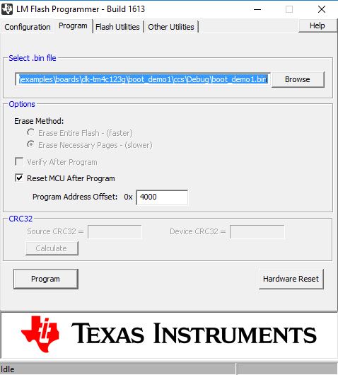
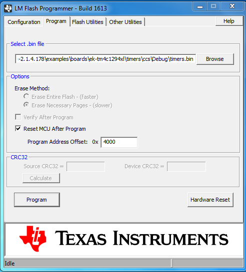
1. How to select my applications hex or bin file in boot_serial code??

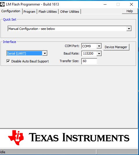
2. How to program the custom board using boot_serial code??

please give me step wise procedure of  programming custom board for first time.

regards,

digvijay

  • Have you not asked, "extremely close variants" of this question - multiple times here - already?    Did those (numerous) responses not satisfy?

    Are you aware that a detailed "User Guide" - aimed specifically at the boot loader - is included w/in the "Documentation directory?"

    It appears now that you are, "Starting from a (near) blank slate" - which must prove frustrating to the, "Team of vendor agents" - who have authored many focused posts (already) - in your behalf...

    This subject has been - repeatedly & well - covered.    Have you employed the forum's Search Box (up top) - to (better) advise "your" (repeating) investigation?

  • Hi,

     Didn't you try the TivaWare boot_serial example? You use the LM flash programmer to load your application firmware like below. First specify the UART interface and next specify the .bin file to upload to the MCU.

  • cb1_mobile said:
    Have you not asked, "extremely close variants" of this question - multiple times here - already?    Did those (numerous) responses not satisfy?

    Are you aware that a detailed "User Guide" - aimed specifically at the boot loader - is included w/in the "Documentation directory?"

    In previous thread related to boot loading i have asked about circuit diagram required for UART , and not the same question as above. I have gone through others threads but none clears my doubts. And i have gone through TivaWare™ Boot Loader pdf , but it does not explain how to use LM FLASH programmer for boot loading. It only mentions that i have to use it. But how do i use it ?? Also nothing have been mentioned about circuit required for boot loading, neither in boot loader pdf nor in datasheet.

    And i don't like to post unnecessary  threads to waste the time and resources of others. Unless there is no other option i don't post thread. So please instead of lecturing and discouraging others simplify your lengthy and complicated documentation (dedicated to the experts) and feel the gaps so that beginners like me can understand and use it and dont have to ask questions here. Anyway it is getting awkward here.

    regards,

    digvijay

  • Charles Tsai said:
     Didn't you try the TivaWare boot_serial example? You use the LM flash programmer to load your application firmware like below. First specify the UART interface and next specify the .bin file to upload to the MCU.

    Respected sir,

    Thank you for the reply. You have said that, i have to specify UART interface and .bin file. In snap you have used boot_demo1.bin file. But what if i have to download other example like timer??

    1. Can i give a path of timer.bin instead of boot_demo1.bin as shown in attached snap??

    2. Also can i use the same method to download uartecho (with and without modification) example from TI-RTOS??

    Regards,

    Digvijay.

  • Had your initial post here (so close to your earlier ones) included such detail (as you've just provided) I would not have responded.

    My post asked 3 questions of you - each intended to,  "Enhance your understanding - lessening "wear/tear" upon vendor agents."      The (single) guiding, "non-question" - cannot  "rise to" a, "lecture."

    It is hard for (any) to know - when "advice" transitions to, "lecturing."    Do "you" not (now) - speak from a substantial, "lectern?"

  • Also i want to know which cable/connector/convertor i have to use for connection between PC and custom board. I am planning on using USB TO SERIAL DB9 BAFO MAKE converter. Will it work??
    regards,
    digvijay
  • This is third time i am receiving reply like this from you. Already i am under pressure of dead lines. I was not expecting these kind of replies from TI.
    And it is serious advice that update your documentation. Only functions, structures etc are given, nothing about step wise procedure, circuit diagrams, connection, cables have been given. If i do not know about procedure to implement the given codes and circuit diagrams(boot loading) , what do i do with functions , structure and some packet handlers?? It is useless to me and very time consuming process.

    Regards,
    Digvijay
  • Hi Digvijay,
    You can use the LM Flash Programmer to download any .bin file (i.e. a simple blinky example if you want). But please go through the boot_demo1.c example and see how it transfers the control back to the bootloader. What I mean is that you need to build some intelligence into your application firmware so that if you want to update your firmware again, the application will transfer the control back to the bootloader. The boot_demo1.c current relies on the switch being pressed as a method to transfer the control back to bootloader so a new firmware can be updated. If you want to upload the uart_echo TI-RTOS example, you need to modify the example first. Otherwise, it will become a one-time update.
  • respected sir,
    Thanks for the reply. That was really helpful. But you have not covered cable part from the reply in same thread. I am again asking the same question.

    Also i want to know which cable/connector/convertor i have to use for connection between PC and custom board. I am planning on using USB TO SERIAL DB9 BAFO MAKE converter. Will it work??
    regards,
    digvijay
  • Hi,
    I think it is your decision to make. We can only provide support for answering questions related to the MCU. I'm not familiar with the USB to Serial DB9 from BAFO. You need to investigate if it suits your need. Does it have a built in usb to uart protocol converter? Does it provide driver for the PC side so the PC can recognize as a virtual COM port? Are you adding a DB9 female connector on your board? What voltage level does this BAFO require? Do you need a MAX232 in between this BAFO and the MCU? These are all the questions you need to answer.

    I will suggest you look at the FT232R from FTDI . This is the popular option.
  • Respected sir,

                            My colleague have used USB to Serial DB9 from BAFO for programming TMS320F2810 using C2000Prog.exe . It provides driver for PC and has usb to usrt converter. It also requires MAX232/MAX3232 on controller side. So i think it will work.

    regards ,

    digvijay