Hello,
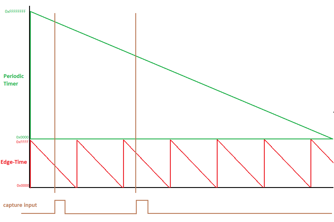
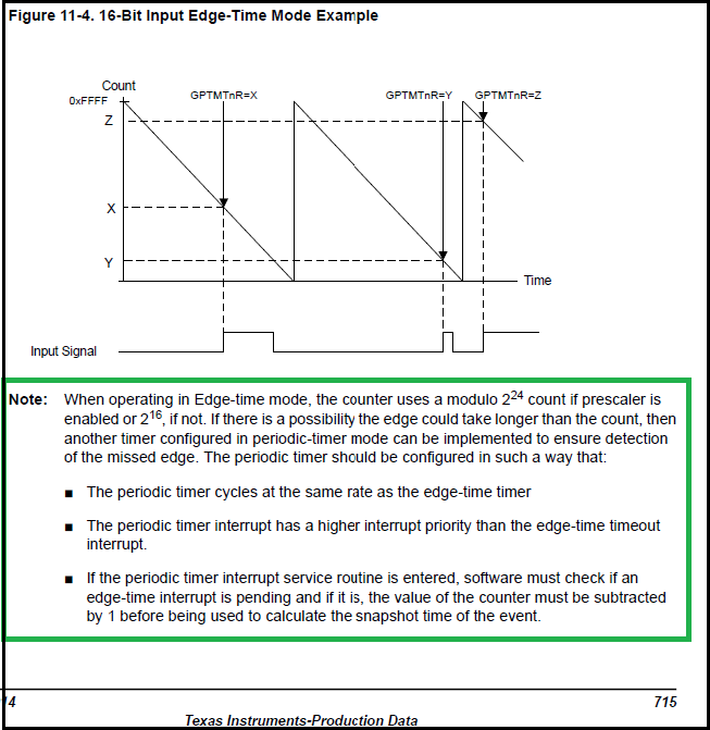
I am working on understanding how the Edge-Time Mode Timer works on the TM4C123GH6PM, in particular, clarification to the note shown below from the datasheet. The idea is to capture an edge which happens to fall outside the 216 or 224 (with prescaler enabled) count values. I know the 32-bit/64-bit timer can be used to generate 248 with a prescaler can be used to count higher time events, however, I want to experiment with using a periodic timer as the note suggests.
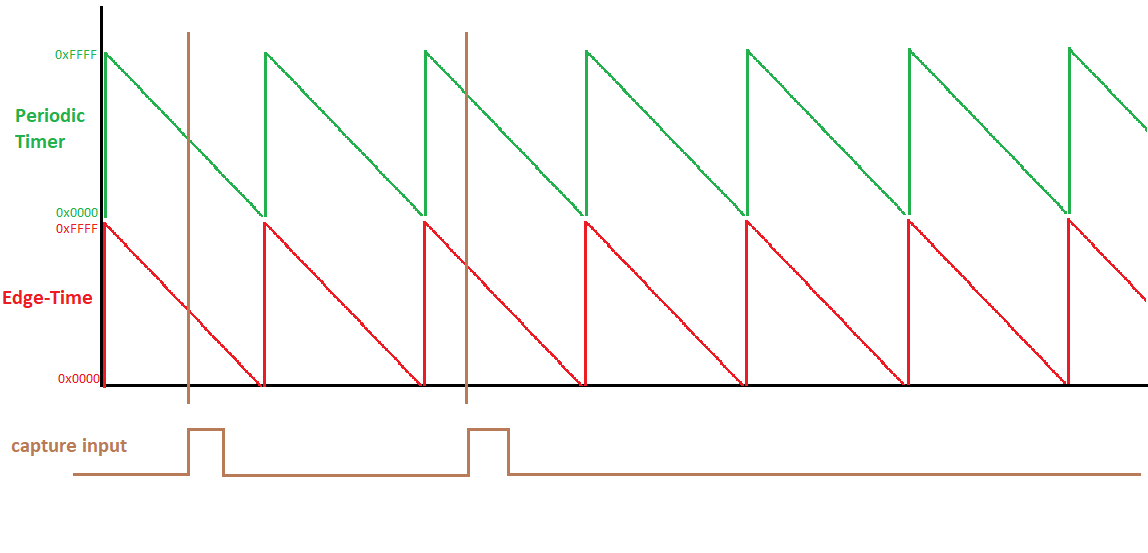
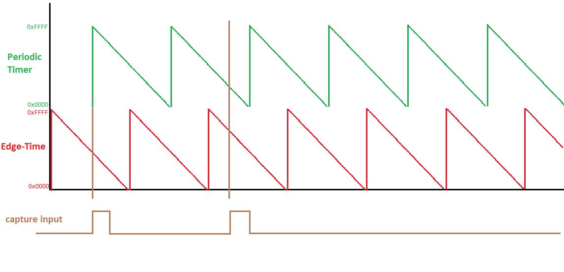
- The first bullet point states "periodic timer cycles at the same rate as the edge-time timer"
- From my understanding, this means to use the same clock source.
- For second bullet point, I don't get why we need the periodic timer needs higher priority
- I don't understand which counter should be subtracted, the peroidic timer or edge-time timer?
Overall I am having a hard time understanding how the periodic-timer helps capture the missing edge.
Thanks,
Fil