This thread has been locked.

If you have a related question, please click the "Ask a related question" button in the top right corner. The newly created question will be automatically linked to this question.

TM4C123GH6PM: PWM PINs

Part Number: TM4C123GH6PM

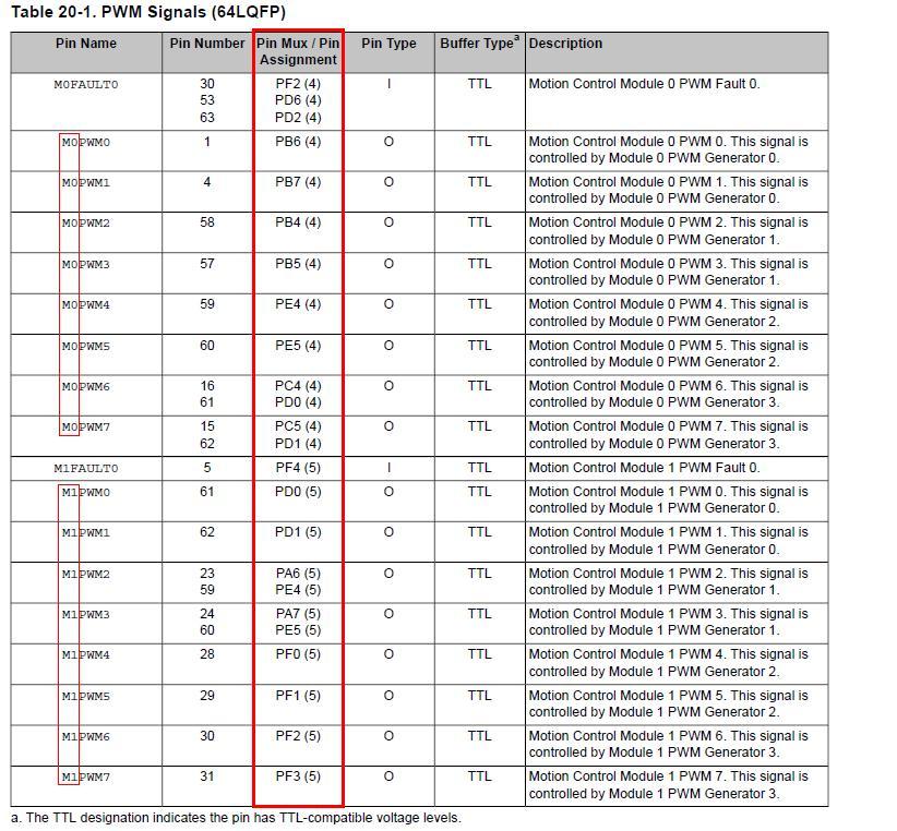
I got PB6 to work as an output using the PWM but other than pin PD0 and PB6, no other pins seem to be able to output, and also for some reason

both pins PB6 and PD0 output when I'm only outputting to PB6, after searching for some answers, I found out that PB6 and PD0 are both connected together,

for compatibility with some other device, but I'm not sure why after trying all other possible pins given  the PCTL table on the datasheet, no signs of output show on

any other pins except for PB6 and PD0? I've also had the suggestion to remove resistors 9 and resistors 10, but shouldn't at least one other pin

be able to output without having to remove these resistors?

  • Mar Mar said:
    shouldn't at least one other pin be able to output without having to remove these resistors?

    True (true) that!      (that redundancy - in honor/reflection -  of  poster's  repetitive  forum ID.)

    Absolutely - obtaining PWM Output - from those pins "falling w/in the MCU's listing of  "PWM Capable" - AND which are "brought out to header pins (on the LPad)  surely  can be  accommodated!

    Presented (here) as (another) "Cb1 Public Service" (in satisfaction of  "Work Release" status) is the Listing of  "ALL (legal) Candidate PWM pins:"

    Note the (colored) highlights: ONLY those pins - listed w/in column 3 - are equipped w/"in-built" PWM functionality.    (Timer pins may be programmed to provide "lesser"  PWM competency.)

    Poster must carefully compare/contrast,  "His/Her chosen pins to insure a "match" to this  "defining/regulating"  chart.

    Note too - the left-most column - which reveals the division of such PWM-Capable pins - into usually (but not always) a  Single PWM Module.   (there are two such modules - denoted as M0 & M1.)   Certain pins (albeit only a few) exhibit "dual citizenship" - able to reside w/in "either" PWM Module.    (yet only "active" - w/in one module - at a time...)   PD0, PD1, PF2 are (some) - but not all - such "dual" pins.

    *** Returning to poster's specifics - it must be that,  "One or more of the required,  "Set-Up/Config. Functions" were "missed" - or applied incorrectly.    (they ARE - rather detailed)    Note that a "competent investigator" picks up on poster's use of  "PCTL table, on the datasheet" - which (likely) suggests that poster employed the (dreaded) "DRM" - thus his "FAILED PROGRAM" - is unfortunately - "To be Expected!"    Poster's hapless "Helper Crüe" - deprived of ANY Code extract to analyze - is left then  ONLY  with this advice option - to poster:

    • move from (assumed) DRM to the far more modern, efficient, result attaining, and LONG PROVEN  "API"
    • if still "troubled" - even after consulting the MANY code examples (found w/in: TWare\Examples\Peripherals\PWM ... AND ... the invaluable, "Driver Library User Guide" (found TWare\docs\) - posters are then advised to:  Post their code here - to insure that, "many may review" - and  (even) advise...

    Note that (several) of the PWM parameters - w/in the API - are "unusual" - and require (sustained) "high focus."     Again - the DL User Guide (earlier specified) provides EXACTING DETAIL.    (even "hand-holding" - I am told...)

  • Thanks,
    my assumption was correct that it had to be true that my code was wrong, and that it was possible to output on other pins,
    I got other pins to work now,
    now I'm puzzled about weather or not I should Remove resistors R9 and R10, I hear that not doing so could result in shorting some pins(using PWM).
  • There should be "absolutely" NO PUZZLE!     Remove those "Plague-Istors" - which sit patiently - just waiting to cause (likely) unrepairable Output Contention!

    W/in the past 3-4 days - I described (our firm's approved method of, "Remove & Tombstone" - even practiced (now) by several of our "giant" firm - consulting clients.     (who just like we - cannot understand - nor accept - how this KNOWN ISSUE - has been permitted - to LINGER for SO LONG!     (simple bag would fix - indeed "inconveniences those ONE or TWO" who (may) seek past "compatibility."   Pity!

    If you click on my forum ID - and scroll thru "recent posts" - you should quickly find the post which describes our approved method of "Banishing Plague-Istors"  while "highlighting the fact that the boards have been, "Restored to Normal/Customary"  (i.e. NO unwanted surprise - LURKS!)

  • Thanks,
    this resolved my issue,
    I tried looking for the post you mentioned, I'm not too familiar with this network,
    I couldn't find it, but no problem, I'm confident I am able to desolder the resistors without
    needing step by step guide.
    It would be nice though just to double check that I'm not missing any details to find the post,
    and It would be worth becoming familiar with this website how to find other's posts.
  • It is unclear if you followed my direction - and "moused over my forum ID" and followed  "recent posts."

    If you (simply) "pull the resistors" there is NO CLEAR indication that such, "Corrective Surgery" - was performed!      This then is the  "none too subtle value" of the more deeply thought,  "Tombstone Process!"     (which "tack solders" (one & only one) resistor lead to its original pad - placing the resistor perpendicular to the pcb (vertical) - w/only one of the resistor's ends soldered.    (i.e. very similar to a "tombstone.")

    This provides "instantly recognizable proof" - that  this "treated LPad" - now meets,  "Normal/Customary" board standards - and the (almost) certain "Death via (deliberate) Output Contention" - has been PREVENTED!

    Should you - like many here - employ "multiple" LPads ... in time - those  MISSED or FORGOTTEN "Plague-Istors"  - will  "Bestow their PAIN!"     Tombstone boards escape that (very) tall (vendor carved) cliff...

  • Thanks,
    glad I got that taken care of.
    This resolved my issue.
  • It is "hoped" that, "Taken care of" is (code) for, "Tombstoned!"      "Down the road" - memory dims - that  "tombstone"  (daily reminds) of such NEED - while keeping your (fixed) board SAFE!