This thread has been locked.

If you have a related question, please click the "Ask a related question" button in the top right corner. The newly created question will be automatically linked to this question.

TM4C1294NCPDT: GPIO output rising and falling edges

Part Number: TM4C1294NCPDT
Other Parts Discussed in Thread: EK-TM4C1294XL

Hi,

I have designed a circuit with a tm4c1294 microcontroller. All 4 SSI interfaces are used

in SPI mode to connect to external peripherals of which 2 are on the same PCB and 2

others are on a seperated PCB connected via short flat band cable.

I am experiencing troubles with the output drive of the GPIO lines. The rising and

falling edges have such slopes that the signals are more like a sinus then a digital

square wave. The result is of course unreliable communication to the external peripheral

at higher bit rates.

I have tried the outputs with external peripheral connected and disconnected. Also

initializing the SSI and running a test on the ek-tm4c1294xl board (not connected) has

a sinus like waveform as output and not a square wave.

Another test I did is just toggling the pa4 and pa5 outputs on the ek-tm4c1294xl

board, also a sinus instead of a square wave (WPU and PP, 2 and 8 mA).

Below are 2 screenshots of 1 MHz and 2 MHz SPI signals. The blue analog waveform is

the clock signal.

Power supply is properly done with 100 nF and 1 uF caps close to the microcontroller

and the SPI connected peripherals.

Checked the +3V3 power rail with the scope, no problems.

Any thoughts ?

Roelof

  • I would be (beyond) astounded if such waveform resulted from your "ek-tm4c1294xl."       Unless earlier "HORRORS" had visited those pins - NO WAY!

    You do not present your "Selected Pins - Set-Up and Config. Code" - which may have been in error - causing such 'Failed Outputs!"

    As is proven here - near daily - anything registers "possible" when a custom pcb is attempted.

    It is (far more likely) that you have: improper scope technique (flawed/failed scope ground),  excessive signal loading  or  insufficient power and/or "FAILED COMMON GROUND CONNECTION" BETWEEN BOARDS!    And this (only if) your "Set-Up & Config. Code" - aimed @ "pins in question" was proper!     (and unfortunately - NOT Provided!)

    NOT to blame the vendor's devices - they are FAR TOO SMART, PRACTICED!     The "one time" user rises to (beyond) PRIME SUSPECT...

    I have a neat photo which illustrates excellent "Scope Technique" - may require a few minutes for staff to find - & present here - coming...

  • And - (yet) another,  "Cb1 Public Service"  duly arrives!    Even after 3 - 05:00 staff arrivals this week!  (03:00 start for moi - this day)

    Note the speed of response from staff (12 minutes! - able to locate, recover & load here!)     SO efficient - and  that after arriving 05:00 (local) CST -  this (and 3 other) mornings - as we "Chase a Big Deal" - against "less knowledgeable/efficient/inspired" (yet always larger) competitors!     (soon to be vanquished competitors - I am told...)    Bravo Staff - now  WHERE IS that "LIKE" Button?

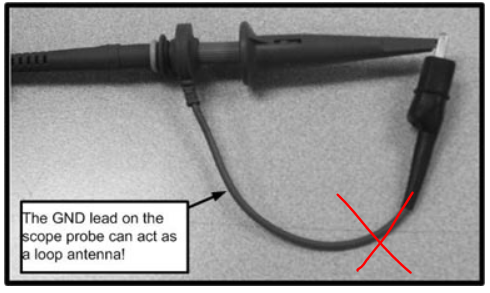
    Photo reveals the "proper" means to make a "reasonably true" scope cap - free from extraneous/impinging signal artifacts/effects.    

    The scope PROBE'S ground lead has been removed - replaced w/ a short/direct, "coiled wire" - which  contacts the scope probe's "Ground  barrel."    Very effective - more so as frequencies rise.

    And: Shown here - for those non-english native - the direction to remove the probe's ground lead - presented visually.

    As earlier noted - if at a "table in Vegas" ...  I'd place a very TALL Stack of chips (again) on  your scope ground being "AWOL" or the  "LOSS of COMMON Ground between boards!"   (Missing and/or inadequate)

  • I am amazed too and looking for some help in this matter. I am not blaming
    any one (except myself if I made a mistake in routing my PCB).
    Not sure if your answer is full of sarcasm or not, anyway it is not help full
    at all.
    And yes I do know how to use a probe to do a measurement.

    Roelof
  • Tell me WHERE you believe "sarcasm" to reside?

    Further - care to reveal how: Failed Pin Set-Up/Config code + Common Ground + Failed probe ground + Inadequate power - "Registers as,  "Not helpful at all?"     Is not YOUR  hostile response - better suited for such label?

    You stated that the vendor's EK board - a highly PRO Board - produced a very similar output! I find that DIFFICULT to (pardon) accept or believe.   (unless - as noted - earlier DAMAGE befell those pins and/or those pins "Set-Up/Config" was "Butchered!")    Again - the (always aiding) pertinent peripheral code - was NOT supplied!

    We "helpers" here have "no knowledge" as to your experience nor background - so YOUR use of, "I do know how to use a probe" FAR BETTER qualifies as "sarcasm" - does it not?

    My attempt - joined by my staff - was to CLEARLY ASSIST - and any REASONABLE READ of the facts - SURELY REVEALS that - to have been  overwhelmingly achieved!

  • Note too - that even after attack - especially after attack - there is a chance that your Scope Probe's signal connection is open and/or flawed!
    No EK board which firm/I have ever seen (and that's well beyond 500!) has ever evidenced what you have presented!
  • Grounding is a good first guess when considering scope shots and board to board connectors.

    Your signal is attenuated as the frequency increases as if you are passing it through a simple lowpass RC filter. Is there any series resistance? All traces act as some capacitance to ground plus the capacitance of your cable.

    For reference, the -3dB frequency is F=1/2piRC. The 3db frequency of your sine wave is around 2MHz. A square wave is made up of many frequencies, and it becomes a sine wave when you filter out the higher frequencies.
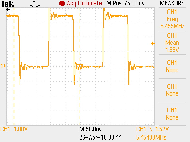
  • Let's see if we can isolate if it is a hardware or software issue. You mentioned pins PA4 and PA5. I created a simple project that runs at 120MHz and bit-bangs PA4 and PA5 at over 5MHz. Import  the project from the attached .zip file and see if your results are similar to what I got in the scope shot below.

    CB1,

    Thanks for the good information on proper scope use. That is likely to help other who see this thread. However, now I am embarrassed that I include a scope picture caught with a probe using a 3" ground clip (Oh the ugly ringing). Anyway, the picture proves the pins are fast, and I have lots of other work to do today.

    EK-GpioToggle.zip

  • Yet - the degree of  "Signal Failure" - as noted here - rises FAR BEYOND simple filter issues - I believe.

    Missed common ground - bad probe - or (especially) FAILED MCU Peripheral "Set-UP/Config" - stand as much more,  "likely suspects."

    Even though - especially though - such crystal clear - spot on diagnosis - is judged by ONE - as not AT ALL Helpful.     (such "not at all" - achieved (only) by poster's so mistaken judgement - to be clear...)

  • Bob,

    Our posts crossed (they were just  "4 minutes" apart.)      As stated - several of our clients employ (many) LPads - making key modifications - and/or employing them in (necessarily) destructive testing.   This is how our  "500 (minimum) LPad and/or EK board review" - extending over the past TEN YEARS (that's just 50/year) - arose.    (and is justified)    

    Never have we noted signals - anywhere close - to poster's presentation.    Poster clearly has (some) MAJOR FAILING - yet the "lack of grace" - tries one's patience.

    Be strong Bob - good and valued as your post is - poster may character it TOO as, "NOT USEFUL - AT ALL!"     Which would be - AGAIN - FAR (very FAR)  from the truth!

    Clearly poster's MCU's Peripheral - be it GPIO or SPI - (MAY) have been improperly configured - OR the Scope or Probe is "distressed" or Common Ground was LOST.

    All of those  Well Considered, Specific, Diagnostic Offerings - Prove EXTREMELY USEFUL - WITHOUT ANY DOUBT!

  • Hi Peter,

    Thank you for responding.
    As you might have noticed from the screen shots I included I am using a
    logic analyzer and not a real oscilloscope. Reason for that is that I did
    not have a scope at hand at the site were I am working (trying to debug
    the problem). I am fully aware of the bandwidth limitation as you mentioned
    and will use my (real analog) oscilloscope to have a look at the signals.
    I just did not think of the bandwidth to be that low at 10 MS/Sec and the
    Nyquist frequency to be at least 5 MHz. But after reading your comment
    and some thinking about it I think you are right. I will confirm it early
    next week when I am back at the site.

    Roelof
  • Hi Bob,

    Thank you for taking the time to respond with an example.
    I have tried it (it does not differ much from the code I used
    in my earlier tests) and it does indeed toggle at 5,5 MHz.
    I also tried it at a much lower frequencies, as low as 215 kHz.
    I found out that the scope function in the logic analyzer is kind
    of useless as it attenuates the signal at a low input frequency.
    At 870 kHz a sinus signal is all that is left of the original
    (I suppose a square wave) input signal. I still have to check it
    with a real oscilloscope.
    But the problem with the unreliable data transfer remains
    to exist so I have to start looking over again.

    I do use the logic function of the analyzer a lot but this was
    the first time of using the analog scope function of it too beyond
    playing with it before. My mistake in interpreting the measurement
    result and not taking note of the limited input bandwidth.
    The fact that the data transfer is more robust at a low(er) frequency
    than a high frequency (2 - 8 MHz) made me belief that the analog
    measurement result was real.

    Roelof
  • OK, at least that is some progress.

    Double check the clock phase and polarity settings between master and slave. In the logic analyzer picture you included above, the slave is clearly outputting data on the falling edge of the clock. Is the TM4C1294 the master? What is one of the slaves that is giving unreliable data transfers? Which mode did you use in the call to SSIConfigSetExpClk()?
  • Bob,

    I too noted w/in poster's "opening post" - which (I now quote): "result is of course unreliable communication to the external peripheral  at higher bit rates."

    That writing is not "distinct or absolute" - yet does suggest that (some) SPI communication had occurred - at (some) lowered bit rates.     (It is noted that all pertinent details (defining "unreliable" & higher bit rates") - somehow - missed that posting.)

    If communication, "Had successfully occurred" - then the "Claim by others" - that the "monitoring device was to blame" - seems imprecise & unlikely!     (unless that monitor was  "ALWAYS Present, Connected - and ONLY SOMETIMES - disrupted"  SPI Communications!)    I judge that   "highly unlikely."     (most such monitoring occurs AFTER Failure has been noted!)

    In years at this - board to board INTERCONNECTS - have proven - BY FAR - the biggest single cause of FAILURE.    In firm's/my defense work - that is especially  (and almost exclusively) true.

    And likely (even) MORE TRUE here - where client-users are working on "One-Off Prototypes" and may not have full access to Proper Equipment and Techniques.      (this poster was (apparently) at client site.)

    You are (very) correct to question if the, "Variability among Slave Devices" - even when - and especially when - bused together - may prove an additional  cause of poster's,  "Unreliable"  communications.

    Yet we must all note that poster, "Toggled PA4 & PA5" (assumed set to GPIO Output) and reported the same  (illegal) waveforms.      This highlights the requirement for Adequate Equipment - especially when in the field -  where, "Failed Field Correction" ...  leads to an (unwanted - expensive)  Return Visit.