This thread has been locked.

If you have a related question, please click the "Ask a related question" button in the top right corner. The newly created question will be automatically linked to this question.

TM4C129XNCZAD: EPI host bus mode address access have problem

Part Number: TM4C129XNCZAD

Hi Champion

My customer used M4 EPI to access SRAM in host bus16 ADMUX mode, they used the setting as below, and the EPI initialization as below:

They found when they access the address, it looks the address need to let shif 1 bit to get the correct output, as below test result.

I also test in TM4C129X DK board and get the same result as customer see in their board.

But we didn't find in the datasheet that the least bit address is not A0, so please give your comments on the problem, Thank you.

I attached the whole project when I test in the DK board.

void Epi_Initialize(void)

{

         // Enable all the GPIO peripherals.

       ROM_SysCtlPeripheralEnable(SYSCTL_PERIPH_GPIOA);

       ROM_SysCtlPeripheralEnable(SYSCTL_PERIPH_GPIOB);

       ROM_SysCtlPeripheralEnable(SYSCTL_PERIPH_GPIOC);

       ROM_SysCtlPeripheralEnable(SYSCTL_PERIPH_GPIOD);

       ROM_SysCtlPeripheralEnable(SYSCTL_PERIPH_GPIOE);

       ROM_SysCtlPeripheralEnable(SYSCTL_PERIPH_GPIOF);

       ROM_SysCtlPeripheralEnable(SYSCTL_PERIPH_GPIOG);

       ROM_SysCtlPeripheralEnable(SYSCTL_PERIPH_GPIOH);

       ROM_SysCtlPeripheralEnable(SYSCTL_PERIPH_GPIOJ);

       ROM_SysCtlPeripheralEnable(SYSCTL_PERIPH_GPIOK);

      ROM_SysCtlPeripheralEnable(SYSCTL_PERIPH_GPIOL);

       ROM_SysCtlPeripheralEnable(SYSCTL_PERIPH_GPIOM);

       ROM_SysCtlPeripheralEnable(SYSCTL_PERIPH_GPION);

       ROM_SysCtlPeripheralEnable(SYSCTL_PERIPH_GPIOP);

       ROM_SysCtlPeripheralEnable(SYSCTL_PERIPH_GPIOQ);

       ROM_SysCtlPeripheralEnable(SYSCTL_PERIPH_GPIOR);

       ROM_SysCtlPeripheralEnable(SYSCTL_PERIPH_GPIOS);

       ROM_SysCtlPeripheralEnable(SYSCTL_PERIPH_GPIOT);


ROM_GPIOPinConfigure(GPIO_PH0_EPI0S0);

         ROM_GPIOPinConfigure(GPIO_PH1_EPI0S1);

         ROM_GPIOPinConfigure(GPIO_PH2_EPI0S2);

         ROM_GPIOPinConfigure(GPIO_PH3_EPI0S3);

         GPIOPinTypeEPI(GPIO_PORTH_BASE,GPIO_PIN_0|GPIO_PIN_1|GPIO_PIN_2|GPIO_PIN_3);


         ROM_GPIOPinConfigure(GPIO_PC7_EPI0S4);

         ROM_GPIOPinConfigure(GPIO_PC6_EPI0S5);

         ROM_GPIOPinConfigure(GPIO_PC5_EPI0S6);

         ROM_GPIOPinConfigure(GPIO_PC4_EPI0S7);

         GPIOPinTypeEPI(GPIO_PORTC_BASE,GPIO_PIN_7|GPIO_PIN_6|GPIO_PIN_5|GPIO_PIN_4);


         ROM_GPIOPinConfigure(GPIO_PA6_EPI0S8);

         ROM_GPIOPinConfigure(GPIO_PA7_EPI0S9);

         GPIOPinTypeEPI(GPIO_PORTA_BASE,GPIO_PIN_6|GPIO_PIN_7);


         ROM_GPIOPinConfigure(GPIO_PG1_EPI0S10);

         ROM_GPIOPinConfigure(GPIO_PG0_EPI0S11);

         GPIOPinTypeEPI(GPIO_PORTG_BASE,GPIO_PIN_1|GPIO_PIN_0);


         ROM_GPIOPinConfigure(GPIO_PM3_EPI0S12);

         ROM_GPIOPinConfigure(GPIO_PM2_EPI0S13);

         ROM_GPIOPinConfigure(GPIO_PM1_EPI0S14);

         ROM_GPIOPinConfigure(GPIO_PM0_EPI0S15);

         GPIOPinTypeEPI(GPIO_PORTM_BASE,GPIO_PIN_3|GPIO_PIN_2|GPIO_PIN_1|GPIO_PIN_0);    


         ROM_GPIOPinConfigure(GPIO_PQ0_EPI0S20);

         ROM_GPIOPinConfigure(GPIO_PQ1_EPI0S21);

         ROM_GPIOPinConfigure(GPIO_PQ2_EPI0S22);

         GPIOPinTypeEPI(GPIO_PORTQ_BASE,GPIO_PIN_0|GPIO_PIN_1|GPIO_PIN_2);


         ROM_GPIOPinConfigure(GPIO_PK7_EPI0S24);

         ROM_GPIOPinConfigure(GPIO_PK6_EPI0S25);

         GPIOPinTypeEPI(GPIO_PORTK_BASE,GPIO_PIN_7|GPIO_PIN_6);


         ROM_GPIOPinConfigure(GPIO_PL4_EPI0S26);

         GPIOPinTypeEPI(GPIO_PORTL_BASE,GPIO_PIN_4);


         ROM_GPIOPinConfigure(GPIO_PB2_EPI0S27);

         ROM_GPIOPinConfigure(GPIO_PB3_EPI0S28);

         GPIOPinTypeEPI(GPIO_PORTB_BASE,GPIO_PIN_2|GPIO_PIN_3);


         ROM_GPIOPinConfigure(GPIO_PN2_EPI0S29);

         ROM_GPIOPinConfigure(GPIO_PN3_EPI0S30);

         GPIOPinTypeEPI(GPIO_PORTN_BASE,GPIO_PIN_2|GPIO_PIN_3);


         ROM_SysCtlPeripheralEnable(SYSCTL_PERIPH_EPI0);

         ROM_EPIModeSet(EPI0_BASE,EPI_MODE_HB16);

         ROM_EPIConfigHB16Set(EPI0_BASE,EPI_HB16_CSCFG_ALE_DUAL_CS,0xff);

         ROM_EPIDividerCSSet(EPI0_BASE, 0, 2);                                                                                   // divide by 4 , 30Mhz , SdRam

         ROM_EPIDividerCSSet(EPI0_BASE, 1, 2);

         //ROM_EPIDividerCSSet(EPI0_BASE, 1, 118);                                                                  // divide by 120 , 1Mhz , IO

         ROM_EPIConfigHB16CSSet(EPI0_BASE, 0, EPI_HB16_MODE_ADMUX | EPI_HB16_ALE_HIGH | EPI_HB16_BSEL | 0x0000FF00);

         ROM_EPIConfigHB16CSSet(EPI0_BASE, 1, EPI_HB16_MODE_ADMUX | EPI_HB16_ALE_HIGH | EPI_HB16_BSEL | 0x07000000);

         ROM_EPIConfigHB16TimingSet(EPI0_BASE, 0, EPI_HB16_PSRAM_256 | EPI_HB16_CAP_WIDTH_2);

         ROM_EPIConfigHB16TimingSet(EPI0_BASE, 1, EPI_HB16_PSRAM_256 | EPI_HB16_CAP_WIDTH_2);

         ROM_EPIAddressMapSet(EPI0_BASE,

                                                                                                        (EPI_ADDR_CODE_SIZE_256B|

                                                                                                         EPI_ADDR_CODE_BASE_NONE|

                                                                                                         EPI_ADDR_PER_SIZE_16MB|

                                                                                                                EPI_ADDR_PER_BASE_C|

                                                                                                                EPI_ADDR_RAM_SIZE_256B|

                                                                                                                EPI_ADDR_RAM_BASE_NONE

                                                                                                                )

                                                                                                       );

}

project0.zip

  • The code is using 16-bit wide mode. The address lines provide addresses A25:A1. A0 is not needed because byte reads are done by selecting either the upper or lower byte of the 16 bit wide data bus.
  • Hi Bob
    Really thanks for your reply, because this question take me for a while to check.
    Could you also suggest where this information you mention in the 129X datasheet? I need to show to customer.

    Eric
  • Hi Eric,
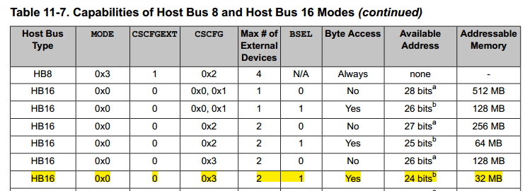
    To be honest, I don't think it is explicitly stated. To me it is intuitive (but I admit that may not be true for everyone). The line from table 11-7 that you posted above show 16 bit data bus, 25 address lines and a 64MB address space. How else can you interpret the address lines other than from A25:A1? A24:A0 would only be 32MB. A25:A0 is 26 address lines. The valid answer for 25 address lines and 64MB address space is A25:A1.
  • Hi Bob

    Correct the configuration setting as below:

    It also same as your comments: For 24 bit address line, and 32MB address space, it should be A24:A1. I will feedback to customer and get their response.

    Thank you!

  • Hi Bob

    After feedback to customer, there have below concern about the datasheet content as below :

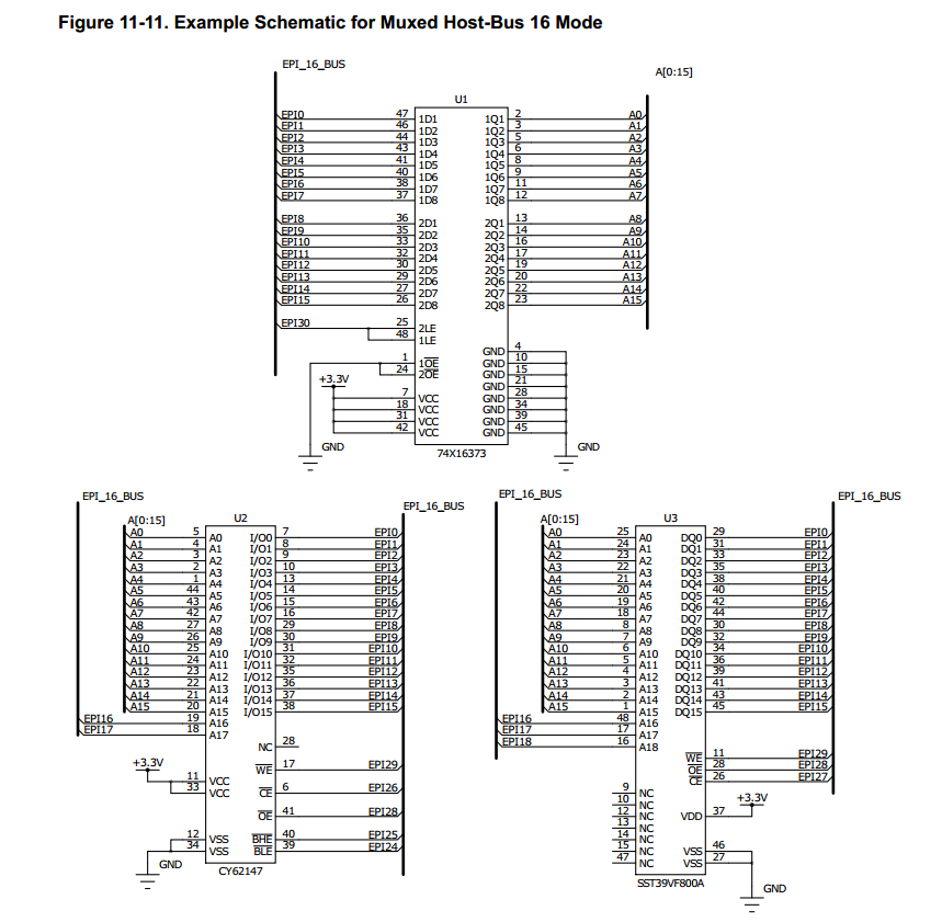
    The example in datasheet still use A0, customer want to know how to explain this?

  • Hi Bob

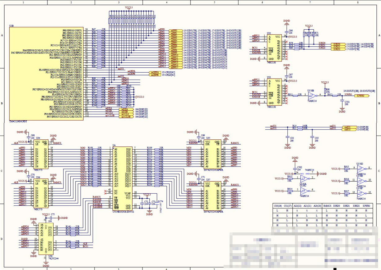
    Below are customer SCH about EPI connect to a 64K * 16 SRAM:

    Customer said he can byte read and write data from 0x C0000000 ~ 0xC001FFFF, so he think A0 is taked effect.

  • I am sorry, I do not see the problem. What is not working for the customer?
  • Hi Bob

    At the begining of the post, customer want to control EPI22, EPI21, EPI20 using address access, but we found the address need to left shift 1 bit. 

    Then as your comments, we think the address line is A1~A24, NOT A0~A23, which A0 is not used in this mode.

    But customer do the test, found he can read write data from 0x C0000000 ~ 0xC001FFFF, which looks A0 is used and work. Meanwhile, in the datasheet, A0 also in the example.

    Whether I explain clearly?

    Appriciate your suggestion !

    - Eric

  • When reading a byte from a 16-bit wide interface, typically all 16 bits are presented on the bus, but the CPU only loads the appropriate byte (high or low) into the register. When writing a single byte on a 16-bit wide bus the byte select signals (BSEL0/BSEL1 not A0) determine which half of the 16-bit bus gets written into the RAM.