This thread has been locked.

If you have a related question, please click the "Ask a related question" button in the top right corner. The newly created question will be automatically linked to this question.

TM4C1290NCPDT: I2C pullup resistor calculations

Part Number: TM4C1290NCPDT

Hi,

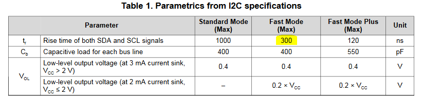
The application uses 1.5kOhm I2C pull up resistors. The I2C is used at 400 kbps data rate.

The rise time on the I2C clock was measured on the scope as 292 ns.

Plugging these numbers into the equation 7 of the I2C Bus Pullup Resistor Calculation app

note, the bus capacitance calculates to 230 pF. 

Does this mean the pull up resistor value is within acceptable range?

Not sure how to calculate the bus capacitance. The layout tool can measure the track capacitance

from the I2C GPIOs on the PCB, though this number reads something like 10 pF on each track.

Thanks,

Priya


  • You may benefit by "Including or Linking" to that, "I2C Bus Pullup Resistor Calc App." Even though - here forever - I've "No Clue" how or where to "find it."

    If there is just one Slave I2C device "on the bus" and tracks are (reasonably) short/direct - it is our experience that "exactness in I2C Pull-Up value's determination" - may prove "over-kill." The value (1K5) you note - for a single slave - seems "Lower" than normal/customary - to me.

    Far more encountered would be: 2K2 - 10K. Lowered values - force more sink current upon both I2C lines of the Master - and upon the SDA line of the Slave - and may (not) produce notable improvement.

    I would suggest that you "Scope Monitor each I2C line - at the Slave's signal pins (or as close as you can reasonably get) being sure to remove the Scope Probe's (usually overly long) Ground Lead - and employ a wire loop - instead.    

    [edit]  I've just noted Vendor Bob's neat  I2C chart - and if those values (are) really correct - you are correct in employing such a (relatively) low value resistor.    

    Firm/I find - however - that the signal "Robustness" under those "higher I2C speeds" suffers a "fall-off" - which is why the "More Eased Resistor specification" - has LONG - worked for us.    It is our opinion that "SPI" is a superior candidate - if normal speed I2C - is deemed,  "Too Slow."    And - there ARE reports of "heating effects" - impacting I2C devices in time (and in "warm ambients")  - due to the higher current flows commanded...

  • The critical measure is if the rise time is less than the maximum allowed for that mode. From table 1 of the application report: http://www.ti.com/lit/an/slva689/slva689.pdf, the maximum rise time for Fast Mode is 300nS. Your 292nS is just fast enough, but you are very close. Now, what is the tolerance of that resistor and what was the actual value of the resistors used when making the rise time measurement? You might want to go with slightly lower resistor values to allow for the variation between resistors.

  • Bob,
    The pull up resistors on the SDA and SCL lines are: RES 1.54K 1/10W 1% 0603. Including this tolerance,
    the bus capacitance falls in the range of 222 pF-226 pF.

    The same resistor was used for the rise time calculations, not sure if it was actually measured.
    Maybe 1.2 kOhm or 1 kOhm might be a better choice?

    Thanks,
    Priya
  • With 1% resistors you are fine. If you need to reduce cost (if you plan to make millions of these) you might go to 1.2K 5%.