This thread has been locked.

If you have a related question, please click the "Ask a related question" button in the top right corner. The newly created question will be automatically linked to this question.

CCS/EK-TM4C123GXL: MPU6050 with Tm4c123gh6pm

Part Number: EK-TM4C123GXL

Tool/software: Code Composer Studio

hi everyone,

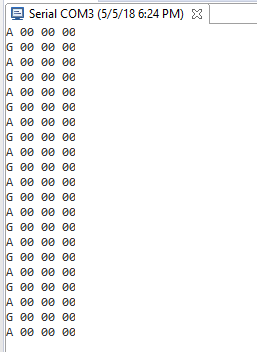
I have been trying to implement MPU6050 Example code on Tiva c launchpad but the readings received are some constant garbage values. Connection is appropriate as the code detects the sensor form the specified address ( 68).

Please check the code file and suggest if any..

/cfs-file/__key/communityserver-discussions-components-files/908/MPU6050.cpp

Thank you 

Regards,

Nanda Kishore

  • Prior to the investment of: 'Time, Effort'  to, "Check the code file & suggest" - is it not preferable for, 'You to advise as to the presence of (external) pull-up resistors - upon SDA/SCL ... and ideally - the presentation of scope caps."

    Those scope caps prove optimum when: they reveal the successful detection of the sensor (via address (0x68)) ... and the capture of a "garbage value."    Such enables a classic,  'A-B'  Test Comparison - which (usually) yields an efficient diagnosis.    Do provide a narrative - describing what value was to be sent to the sensor - and what was returned.   (which you class as "garbage.")

    It is unclear as to your meaning, "Constant garbage values" - does this suggest that all such (garbage) values are "unchanging?"    (thus constant)

    How do you conclude that these values are "garbage?"       What are your test conditions & expectations - and by what means were these chosen?

  • hi,

    firstly, I didn't use oscilloscope to test the hardware but mpu6050 is proved working when I implemented with arduino without pull-up resistors. And the readings I receive are unchanging..  

    sorry for mentioning garbage values .. previous experiments have shown some different value but now the readings are all zeros

    i.e for this code

              UARTprintf("A %02d %02d %02d\n", fGyro[0], fGyro[1], fGyro[2]);

             UARTprintf("G %d %02d %02d\n", fAccel[0], fAccel[1], fAccel[2]);

    the reading i got is

    thank you

    Regard,

    Nanda Kishore

  • Nanda Kishore Moduga said:
    mpu6050 is proved working when I implemented with arduino without pull-up resistors.

    You are presenting a VERY WEAK case for, "Rejecting the (necessary) employ of Pull-Up Resistors."      You offer up - "A past observation - achieved upon a completely different board - and one which I suspect - DID include pull-up resistors.     (most such Arduino boards - in our experience - employ pull-up Rs upon their I2C lines)

    Thus - with the rejection of Pull-Up resistors - and NO Scope Traces - can you (fairly) expect those here - to invest significant time & effort - in your behalf?

    The (very fact) that your (now explained) "garbage values" - register at/near Ground -  EVEN FURTHER ARGUES -  for the use of  External Pull-Up Resistors!

  • hi

    Thank you for the early reply.
    However the same reading(zeros) I found even after including External Pull-up resistors of 4.7k ohms.

    Regards,
    Nanda Kishore
  • That proves an awfully quick implementation of both resistors!     Where did you connect those resistors - and "how" were they "pulled up?"

    How are you powering your Sensor Board?       And ... is there a "Checked and Re-Checked" absolutely solid "COMMON GROUND" BETWEEN YOUR MCU BOARD AND SENSOR BOARD?    REALLY?

  • Hello Nanda,

    I agree with cb1, we still need to see scope captures of the SDA and SCL lines to help debug this.
  • Hello cb1 ,Ralph,

    I appreciate your quick reply.

    However we do not posses a scope at the moment .

    I have connected 4.7k ohm resistor each to the SCL and SDA through 5V. Sensor board is powered up with the 5V and GND from the MCU .
    SCL-- PB2
    SDA--PB3
    and I'm sure the Common ground is super solid between them.

    And I have done my best to implement. But not sure whether I have done any mistakes in the code. Please suggest if any.
  • Feel your pain - yet cannot you,  "Lessen the Demands upon your crack "Helper Crüe" by organizing & presenting the following:

    • links to the key pages of your Sensor Manual - so that (myself/Vendor's Ralph/others) may (better) understand (i.e. somewhat understand) your Sensor's (real) requirements.    Providing (just) the entire spec - forces EACH HELPER to scroll thru the manual - WASTING an ENORMOUS AMOUNT of Time - which could be more effectively directed - in your behalf!
    • briefly describe what your, (Order of Code) "Intends to Accomplish" - on a "Function by Function Basis."    Indeed this adds to (your) workload - yet consider that EACH HELPER - is "DOOMED" to repeat that effort - should you not provide that vital guidance
    • it proves best if you describe, "How you chose the values" - which you send to the Sensor - in the attempt to recover 'needed data.'    (i.e. usually such sensors are 'Register Based' - and registers uniquely contain special data - requiring their proper 'addressing' (and sometimes - even Set-Up) to "Extract that (particular) Register's, Sensor Data.")
    • it is always wise to show consideration for your Helpers - even those nameless/faceless outsiders - who expend vast amounts of time/energy - in the attempt to be of (some) service...

  • Hi,

    Is this MPU650.cpp from Tivaware? There is MPU650.c and MPU650.h at "C:\ti\TivaWare_C_Series-2.1.3.156\sensorlib".

    -kel
  • Markel Robregado said:
    Is this MPU650.cpp from Tivaware?

    Both poster's Subject Line - and the body of his opening message - clearly note  "MPU6050."

    Your suggestion is 'beyond a typo' ... Do you know something - the rest of us - do not?

  • Hi cb1,

    The file that he is using is MPU6050.cpp from the download link. However, I found no MPU650.cpp at Tivaware. What there is mpu6050.c and mpu6050.h at Tivaware sensorlib folder. I compared the MPU650.cpp that he is using and mpu650.c from Tivware and it is different.

    So, I think using mpu650.c and mpu650.h from Tivaware would work with Tiva Launchpad. Since TI would most likely have tested the code library before releasing the Tivaware.

    -kel
  • Hi Markel,

    The file I uploaded contains c code for mpu6050 and I have used it as a  ".c" while implementing  but unfortunately I saved it as ".cpp"  in the editor only and I'm really sorry for that.

    As you mentioned that mpu6050.c and mpu6050.h from sensorlib folder: Yes , obiviously the code in the downloaded link(MPU6050.cpp) and mpu6050.c from sensorlib are totally different as the uploaded code is the main one to implement(debugged) while the mpu6050.c from sensorlib folder is the supporting library.

    Thnak you 

    Regards,

    Nanda Kishore

  • That's way too 'sensor specific' for (most helpers) here.     Much Thanks to poster Markel for his clarification - appreciated.

    I must ask - again - that poster make (some) effort to comply  w/that requested during the 05 May (3:08/15:28) posting.

    Minus that - and along w/the absence of scope caps - the demands upon the "helper crüe" appear excessive!      (Seriously  - are we to: Search, Find, Page thru & (then) Analyze ... Really?)

  • Hello cb1_,

    I apologize for the late reply.

    Please check the attached files for info on sensor MPU6050. 

    MPU-6000-Register-Map1.pdf


    The code I used : ( Due to some unknown problem i cant directly paste the code , please find the code in the file below.)

    #include <stdbool.h>
    #include <stdint.h>
    #include <stdlib.h>
    #include <stdio.h>
    #include <stdarg.h>
    #include "sensorlib/i2cm_drv.h"
    #include "sensorlib/hw_mpu6050.h"
    #include "sensorlib/mpu6050.h"
    #include "inc/hw_ints.h"
    #include "inc/hw_memmap.h"
    #include "inc/hw_sysctl.h"
    #include "inc/hw_types.h"
    #include "inc/hw_i2c.h"
    #include "inc/hw_memmap.h"
    #include "inc/hw_types.h"
    #include "inc/hw_gpio.h"
    #include "driverlib/debug.h"
    #include "driverlib/interrupt.h"
    #include "driverlib/i2c.h"
    #include "driverlib/i2c.h"
    #include "driverlib/sysctl.h"
    #include "driverlib/gpio.h"
    #include "driverlib/pin_map.h"
    #include "uartstdio.h"
    
    tI2CMInstance g_sI2CMSimpleInst;
    
    volatile bool g_bMPU6050Done;


    void MPU6050Callback(void *pvCallbackData, uint_fast8_t ui8Status) {
        if(ui8Status != I2CM_STATUS_SUCCESS){
        }
        g_bMPU6050Done = true;
    }
    
    void I2CMSimpleIntHandler(void)
    {
        //
        // Call the I2C master driver interrupt handler.
        //
        I2CMIntHandler(&g_sI2CMSimpleInst);
    }
    
    
    void MPU6050Example(void) {
        float fAccel[3], fGyro[3];
        tI2CMInstance sI2CInst;
        tMPU6050 sMPU6050;
    
        g_bMPU6050Done = false;
        MPU6050Init(&sMPU6050, &g_sI2CMSimpleInst, 0x68, MPU6050Callback, 0);
        while(!g_bMPU6050Done){
        }
    
        g_bMPU6050Done = false;
        MPU6050ReadModifyWrite(&sMPU6050, MPU6050_O_ACCEL_CONFIG, ~MPU6050_ACCEL_CONFIG_AFS_SEL_M, MPU6050_ACCEL_CONFIG_AFS_SEL_4G, MPU6050Callback,0);
        while(!g_bMPU6050Done){
        }
    
        while(1) {
            g_bMPU6050Done = false;
            MPU6050DataRead(&sMPU6050, MPU6050Callback, 0);
            while(!g_bMPU6050Done) {
            }
            MPU6050DataAccelGetFloat(&sMPU6050, &fAccel[0], &fAccel[1], &fAccel[2]);
            MPU6050DataGyroGetFloat(&sMPU6050, &fGyro[0], &fGyro[1], &fGyro[2]);
            UARTprintf("A %02d %02d %02d\n", fGyro[0], fGyro[1], fGyro[2]); // printing value on serial monitor
            SysCtlDelay(16000000/3);
            UARTprintf("G %02d %02d %02d\n", fAccel[0], fAccel[1], fAccel[2]); // Prinitng values on serial monitor
            SysCtlDelay(16000000/3);
        }
    }
    
    int main() {
        SysCtlClockSet(SYSCTL_SYSDIV_4 | SYSCTL_USE_PLL | SYSCTL_OSC_MAIN | SYSCTL_XTAL_16MHZ);
        SysCtlPeripheralEnable(SYSCTL_PERIPH_UART0);
        SysCtlPeripheralEnable(SYSCTL_PERIPH_GPIOA);
        GPIOPinConfigure(GPIO_PA0_U0RX);
        GPIOPinConfigure(GPIO_PA1_U0TX);
        GPIOPinTypeUART(GPIO_PORTA_BASE, GPIO_PIN_0 | GPIO_PIN_1);
        UARTStdioConfig(0, 115200, SysCtlClockGet());
        SysCtlPeripheralEnable(SYSCTL_PERIPH_I2C0);
        SysCtlPeripheralReset(SYSCTL_PERIPH_I2C0);
        SysCtlPeripheralEnable(SYSCTL_PERIPH_GPIOB);
        GPIOPinConfigure(GPIO_PB2_I2C0SCL);
        GPIOPinConfigure(GPIO_PB3_I2C0SDA);
        GPIOPinTypeI2CSCL(GPIO_PORTB_BASE, GPIO_PIN_2);
        GPIOPinTypeI2C(GPIO_PORTB_BASE, GPIO_PIN_3);
        I2CMasterInitExpClk(I2C0_BASE, SysCtlClockGet(), true);
        HWREG(I2C0_BASE + I2C_O_FIFOCTL) = 80008000;
       I2CMInit(&g_sI2CMSimpleInst, I2C0_BASE, INT_I2C0, 0xff, 0xff, 16000000);
    
        MPU6050Example();
        return(0);
    }
    

    please suggest if any changes required.

    Thank you

    Regards, 

    Nanda Kishore

  • Hello Nanda,

    When it comes to interfacing devices to I2C and SPI, it is very hard to tell what is wrong without seeing the communication of the lines. Most of these issues are usually very quick to solve when we can actually see what is being transmitted and/or received.

    The mpu6050 file provided with sensorlib should handle the sensor properly but if there are issues, then we rely on seeing scope captures to be able to properly help solve them. Working blind does neither us (both TI and our knowledgeable community members) nor you any good unfortunately, so I really must insist that you find access to a scope or get a logic state analyzer in order to provide us some captures.
  • Hello Nanda,

    Have you resolved this issue or at least gotten access to an oscilloscope to provide us feedback on the I2C line communication?