This thread has been locked.

If you have a related question, please click the "Ask a related question" button in the top right corner. The newly created question will be automatically linked to this question.

CCS/EK-TM4C1294XL: ADC not running at 2MSPS (capped at 1MSPS)

Part Number: EK-TM4C1294XL

Tool/software: Code Composer Studio

I'm facing some difficulties regarding setting the ADC to 2MSPS. From what I've read on the datasheet, in order to achieve maximum performance, a clock of 32MHz must be supplied to the ADC.

So I configured the ADC this way

void config_ADC0(void)
{
    ROM_GPIOPinTypeADC(GPIO_PORTK_BASE, GPIO_PIN_0);

    ROM_ADCReferenceSet(ADC0_BASE, ADC_REF_INT);

    ROM_ADCSequenceConfigure(ADC0_BASE, 3, ADC_TRIGGER_TIMER, 0);

    ROM_ADCSequenceStepConfigure(ADC0_BASE, 3, 0, ADC_CTL_CH16 | ADC_CTL_IE | ADC_CTL_END);

    ROM_ADCHardwareOversampleConfigure(ADC0_BASE, 0);

    //480MHz PLL / 15 = 32MHz = 2MSPS
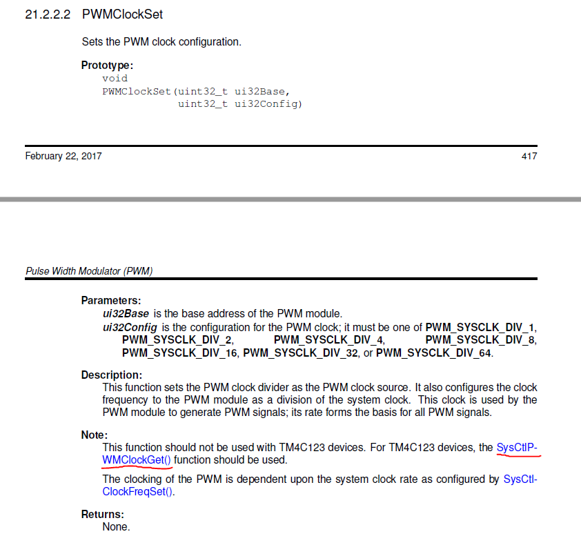
    ADCClockConfigSet(ADC0_BASE, ADC_CLOCK_SRC_PLL | ADC_CLOCK_RATE_FULL, 15);

    ROM_ADCSequenceEnable(ADC0_BASE, 3);

    ROM_IntDisable(INT_ADC0SS3);
    ROM_ADCIntDisable(ADC0_BASE, 3);
    ROM_IntPendClear(INT_ADC0SS3);
    ROM_ADCIntClear(ADC0_BASE, 3);

    ROM_IntEnable(INT_ADC0SS3);
    ROM_ADCIntEnable(ADC0_BASE, 3);
}

And configured the Timer0 to be the trigger (counting at 2MHz speed). But the ADC speed is capped at 1MHz, even when I use ADC_TRIGGER_ALWAYS instead. The system clock is 120MHz with 480MHz PLL.

I'm using these functions and a logic analyser to see the actual speed:

void ADC0SS3IntHandler(void)
{
    ROM_ADCIntClear(ADC0_BASE, 3);

    //ROM_ADCSequenceDataGet(ADC0_BASE, 3, g_adc0Reading);

    ROM_GPIOPinWrite(GPIO_PORTA_BASE, GPIO_PIN_4, g_flagAdc0 ? GPIO_PIN_4 : 0x00);

    g_flagAdc0 = !g_flagAdc0;
}

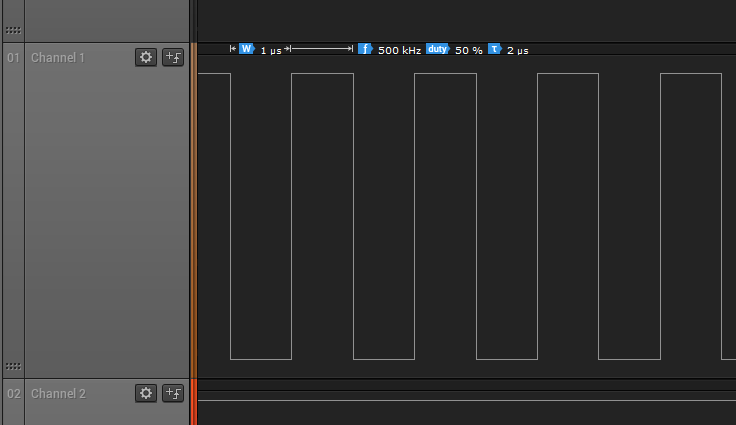
The ADC frequency is 2x the output pin frequency. The only way I could achieve a little higher than 1MSPS (~1.2MSPS unstable) was when I divided the PLL frequency by 7 (resulting a 68MHz for the ADC), but that doesn't make sense. What can I do to achieve 2MSPS?

  • Could the issue be in your timer configuration?
  • I am also seeing only 1MSPS. Let me dig into it.
  • Bob Crosby said:
    Could the issue be in your timer configuration?

    I don't think so, because the timer works with frequencies below 1MHz. And the problem also occurs with always trigger. At least I've tested with those two methods.

    Bob Crosby said:
    I am also seeing only 1MSPS. Let me dig into it.

    That's interesting...I'll wait for your findings, because I just ran out of ideas...

  • Sorry, there is an issue with the documentation. The ADC converter clock is really PLL VCO divided by 2, then divided by the value in the CLKDIV field (CLKDIV+1)  of the ADCCC register. You cannot get 32MHz ADC clock running the PLL VCO at 480MHz, but running the PLL VCO at 320MHz, you can get 2MSPS by using divide by 5.

    The issue is further complicated by the fact that at 2MSPS there is not enough time to use TivaWare calls in the interrupt service routine to toggle a GPIO pin and clear the interrupt. (Much less, read and store the sample.) In the example below I replaced some TivaWare calls with direct register writes to avoid the overhead of the subroutine calls.

    //*****************************************************************************
    //
    //
    // Copyright (c) 2012-2018 Texas Instruments Incorporated.  All rights reserved.
    // Software License Agreement
    // 
    // Texas Instruments (TI) is supplying this software for use solely and
    // exclusively on TI's microcontroller products. The software is owned by
    // TI and/or its suppliers, and is protected under applicable copyright
    // laws. You may not combine this software with "viral" open-source
    // software in order to form a larger program.
    // 
    // THIS SOFTWARE IS PROVIDED "AS IS" AND WITH ALL FAULTS.
    // NO WARRANTIES, WHETHER EXPRESS, IMPLIED OR STATUTORY, INCLUDING, BUT
    // NOT LIMITED TO, IMPLIED WARRANTIES OF MERCHANTABILITY AND FITNESS FOR
    // A PARTICULAR PURPOSE APPLY TO THIS SOFTWARE. TI SHALL NOT, UNDER ANY
    // CIRCUMSTANCES, BE LIABLE FOR SPECIAL, INCIDENTAL, OR CONSEQUENTIAL
    // DAMAGES, FOR ANY REASON WHATSOEVER.
    // 
    //
    //*****************************************************************************
    
    #include <stdint.h>
    #include <stdbool.h>
    #include "inc/hw_types.h"
    #include "inc/hw_ints.h"
    #include "inc/hw_adc.h"
    #include "inc/hw_memmap.h"
    #include "driverlib/sysctl.h"
    #include "driverlib/gpio.h"
    #include "driverlib/adc.h"
    #include "driverlib/timer.h"
    #include "driverlib/interrupt.h"
    
    
    #define USER_LED1  GPIO_PIN_0
    #define USER_LED2  GPIO_PIN_1
    void init_TIMER(void);
    void init_ADC(void);
    
    uint32_t ui32SysClock;
    
    int
    main(void)
    {
    
        //
        // Run from the PLL at 120 MHz.
        //
        ui32SysClock = SysCtlClockFreqSet((SYSCTL_XTAL_25MHZ |
                                           SYSCTL_OSC_MAIN |
                                           SYSCTL_USE_PLL |
                                           SYSCTL_CFG_VCO_320), 120000000);
    
        SysCtlPeripheralEnable(SYSCTL_PERIPH_TIMER0);  //Enable the clock to TIMER0
        SysCtlPeripheralEnable(SYSCTL_PERIPH_ADC0);    //Enable the clock to ADC module
        //
        // Enable and wait for the port to be ready for access
        //
        SysCtlPeripheralEnable(SYSCTL_PERIPH_GPIOE);
        SysCtlPeripheralEnable(SYSCTL_PERIPH_GPION);
        while(!SysCtlPeripheralReady(SYSCTL_PERIPH_GPION))
        {
        }
        
        //
        // Configure the GPIO port for the LED operation.
        //
        GPIOPinTypeGPIOOutput(GPIO_PORTN_BASE, (USER_LED1|USER_LED2));
    
        init_ADC();
        init_TIMER();
        IntMasterEnable();
        TimerEnable(TIMER0_BASE, TIMER_A); // Start everything
        //
        // Loop Forever
        //
        while(1)
        {
    //        GPIOPinWrite(GPIO_PORTN_BASE, (USER_LED1|USER_LED2), 0);
        	HWREG(GPIO_PORTN_BASE + 4) = 0;
        }
    }
    
    void init_TIMER()
    {
        TimerConfigure(TIMER0_BASE, TIMER_CFG_SPLIT_PAIR | TIMER_CFG_A_PERIODIC);
        // Set sample frequency to 2MHz (every 62.5uS)
        TimerLoadSet(TIMER0_BASE, TIMER_A, 40 - 1);   //TODO: Timer Load Value is set here
        TimerControlTrigger(TIMER0_BASE, TIMER_A, true);
        TimerControlStall(TIMER0_BASE, TIMER_A, true); //Assist in debug by stalling timer at breakpoints
    }
    
    void init_ADC()
    {
        GPIOPinTypeADC(GPIO_PORTE_BASE, GPIO_PIN_2);
        SysCtlDelay(80u);
    
        // Use ADC0 sequence 0 to sample channel 0 once for each timer period
        ADCClockConfigSet(ADC0_BASE, ADC_CLOCK_SRC_PLL | ADC_CLOCK_RATE_FULL, 5);
    
        SysCtlDelay(10); // Time for the clock configuration to set
    
        IntDisable(INT_ADC0SS0);
        ADCIntDisable(ADC0_BASE, 0u);
        ADCSequenceDisable(ADC0_BASE,0u);
        // With sequence disabled, it is now safe to load the new configuration parameters
    
        ADCSequenceConfigure(ADC0_BASE, 0u, ADC_TRIGGER_TIMER, 0u);
        ADCSequenceStepConfigure(ADC0_BASE,0u,0u,ADC_CTL_CH0 | ADC_CTL_END | ADC_CTL_IE);
        ADCSequenceEnable(ADC0_BASE,0u); //Once configuration is set, re-enable the sequencer
        ADCIntClear(ADC0_BASE,0u);
        ADCIntEnable(ADC0_BASE, 0u);
        IntEnable(INT_ADC0SS0);
    
    }
    
    void ADC0SS0IntHandler(void)
    {
    	HWREG(GPIO_PORTN_BASE + 4) = 1;
    //	GPIOPinWrite(GPIO_PORTN_BASE, (USER_LED1|USER_LED2), USER_LED1);
        HWREG(ADC0_BASE + ADC_O_ISC) = 1 << 0;
    //    ADCIntClear(ADC0_BASE, 0);
    }
    

  • Now it is working, thank you Bob! I suspected that I would have to write the registers directly. But that's no problem, as I am going to use hardware oversampling (>=16).

    And, speaking of documentation issues, I found a small error in the TivaWare Peripheral Driver Library user's guide:

    I think it should be SysCtlPWMClockSet().

    Thanks again Bob for your help!