This thread has been locked.

If you have a related question, please click the "Ask a related question" button in the top right corner. The newly created question will be automatically linked to this question.

EK-TM4C123GXL: ISR gets triggered more than planned

Part Number: EK-TM4C123GXL

Hi,

I have written a working interrupt driven SSI to communicate with my Winbond flash. Below is the pseudo code:

===========================================================================================

// Transfer data bytes between master and slave

ssi_tranfer fuction {

  • pull SS low
  • SSIIntEnable(SSI0_BASE, SSI_TXFF | SSI_RXFF | SSI_RXTO);
    • Interrupt should start occurring here ...
  • while loop, wait for SS line to be high (will be pulled high once the data transaction is completed in the ISR)

}

// The interrupt handler for SSI

SSI ISR {

Check and save the interrupt status then clear it

if (status & (SSI_RXFF | SSI_RXTO)) {

while (1) {

keep reading the RX FIFO

if RX FIFO empty, break the loop

if done receiving required data (RX byte count reaches 0), disable SSI_RXFF

}

if (all required data bytes has been transmitted and received) {

Pull SS high

}

}

if (status & SSI_TXFF) {

for loop (up to 8 times to fill up the TX FIFO) {

if done transmitting required data (TX byte count reaches 0), disable SSI_TXFF

if TX FIFO full, break the loop

}

}

}

============================================================================================


I will use an example to illustrate my problem, lets say when I want to read the device id and manufacturer id of the

winbond flash. The flash requires the master to send WB_READ_ID followed by 3 bytes of 0x00, then the flash will

spit out the device id + manufacturer id.

Below is a diagram to illustrate the transfer:

XX = don't care

    // Transmitting 4 data bytes and expects two bytes of device id + manufacturer id

    TX                                         RX   
    WB_READ_ID                   XX
    0x00                                    XX
    0x00                                    XX
    0x00                                    XX

    // Master needs to drive clock to allow man_id and dev_id to be shifted out

    0x00                                    man_id
    0x00                                    dev_id

In order to read the device id + manufacturer id, my code will / should:

  • Flag SSI_TXFF since the TX FIFO is initially empty
  • Enters ISR (1st time)
  • load up the 6 data bytes
    • WB_READ_ID
    • 0x00
    • 0x00
    • 0x00
    • 0x00
    • 0x00
  • TX count reaches 0 meaning no more data to transmit
  • Disable the TX interrupt
  • Leaves ISR

  • Flag SSI_RXFF as slave has received those 6 bytes and transmitted 6 bytes back to the master
  • Enters ISR (2nd time)
  • read the RX FIFO, 6 bytes
    • XX
    • XX
    • XX
    • XX
    • man_id
    • dev_id
  • RX count reaches 0 meaning no more data to receive
  • Disable RX interrupt
  • pull SS HIGH
  • leaves ISR

Breaks the while loop that is waiting for SS to be high in ssi_tranfer fucntion

program ends.

As one can see, according to the logic of my code, in this case, I should only enter the ISR two times. When

I step-debug my code(insert breakpoint in the ISR), I was able to see the program enter exactly twice. However,

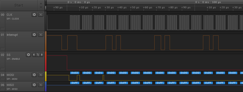
when I do a full run, I get 3 ISR entries which is weird (I inserted a counter to keep the count of ISR entry, and I also

tried to toggle a gpio to monitor the entry / exit of ISR using logic analyzer).

Is there something that I am not understanding correctly about my code or the interrupt mechanism of cortex m4 ...etc?

Best Regards and Thanks in advance!

Jacky

  • Your logic analyzer image shows a good picture of what is going on. The first interrupt is because the TX FIFO is empty. The second interrupt is the RXFF. This interrupt occurs when the receive FIFIO is half full. As you see, it occurs after the fourth transfer. Your interrupt routine empties the RX FIFO of the four bytes before the fifth and sixth bytes are received. After the fifth and sixth bytes are received, no more bytes are received and after some time you get the RX time out interrupt.

    You would be better served if when you setup a command sequence with the flash you use "volatile" global variables for the number of bytes you intend to transmit and receive. You may also need to setup global variables for pointers to the transmit buffer and to the receive buffer. And finally, a "volatile" global variable for when the reception is complete (SSI busy flag).

    Taking your ID read as an example, you create a routine to start transmission which you pass to it a length (number of bytes to send and receive) a pointer to the TX buffer and a pointer to the RX buffer. This function, sets your global volatile flag to say the SSI is now busy (If it was already busy, you should return an error) and then it initializes the interrupt routine TX count to 6, the interrupt RX count to 6 and the interrupt routine's copy of the TX buffer and RX buffer pointers. It then enables the TXFF, RXFF and RXTO interrupts.

    The interrupt routine occurs because the TX FIFO is empty. It loads the TX FIFO and increments the pointer to the TX buffer and decrements the TX count. In this case, the FIFO count becomes zero before the TXFIFO is full, so the TXFF interrupt is disabled. If the number of bytes to transfer was greater than 8, the interrupt routine would leave the TXFF interrupt enabled. Once the TX FIFO became half empty, you would get another TXFF interrupt and the interrupt routine could stuff the next 4 bytes into the FIFO.

    Once four values have been transferred, you get a RXFF interrupt. The receive routine reads the FIFO and stores the data using the RX buffer pointer. It also decrements the expected RX count. Since only four values are available, the RX count is left at 2 and the interrupt routine returns without disabling the interrupts or clearing the SSI busy flag variable.

    After you receive two more bytes, and the timeout time elapses, you get the RXTO interrupt. The interrupt routine reads two more bytes and stores them at the end of the RX buffer. It also decrements the RX count. Seeing that the RX count has decremented to zero, the interrupt routine disables the RXFF and the RXTO interrupts. It also clears your SSI busy flag variable.

    Once the main routine starts the transfer, it lets the interrupt handler do all of the work. The main routine then can poll the SSI busy flag. When it becomes clear, the main routine can read the data in the RX buffer. Also it can start the next transfer.

    This method will work for any size of data transfer. The use of the FIFOs gives more time for the interrupt routine to respond before the risk of losing data.
  • Hi Bob,

    Thank you very much for the detailed explanation. I just have a few more things I would like to clarify.

    1. After your explanation and further analysis on the analyzer screenshot, if I understand correctly, the data will begin transmitting right after the first byte is sent to the TX FIFO and the data transfer between the master and the slave will keep on going even if an interrupt is triggered or currently happening?

    2. What is the reason behind making the global count variables "volatile"? Do they get optimized away somehow? If so, where could that be happening?

    Thanks,

    Jacky
  • Just to make sure I am fully understanding the interrupt trigger, here is another analyzer screenshot showing the reading of 256 bytes of data.

    So the first 4 bytes 0x03 0x00 0x01 0x00 are command / address bytes which means reading bytes from starting address of 0x000100. Since the flash memory is mostly empty. most of the return bytes are 0xFF.

    So initially, since the TX FIFO is empty, the TX interrupt is fired. Then there is another interrupt which occurred between the 3rd and 4th data byte which I believe is, again, the TX interrupt since the 4th data byte has left the TX FIFO (MOSI line gets the 4th data byte slightly later after it leaves the FIFO) which makes TX FIFO half full or less, so the TX FIFO is filled again. Then immediately after, RX interrupt is triggered since 4 data bytes has been received. Then the same thing repeats, TX, RX interrupt ... Is my understanding correct?

    Thanks,

    Jacky

  • Hi Jacky,
    Yes, your understanding is correct!
  • Jacky Wang43 said:
    2. What is the reason behind making the global count variables "volatile"? Do they get optimized away somehow? If so, where could that be happening?

    Declaring a variable as "volatile" tells the optimizer to not eliminate any reads or writes to that variable. When a variable is used in two different threads, such as in the main thread and in an interrupt routine, it may be changed unexpectedly. If the variable is not declared volatile, the optimizer may, for example, read the variable into a register once, then only check the register value without rereading the RAM location again. In the extreme case, the optimizer may totally eliminate all reads and writes to a variable if it does not see that variable being "used" in a thread. A classic example of this is a software delay such as an empty for loop:

    for(i = 0; i < 100; i++);