This thread has been locked.

If you have a related question, please click the "Ask a related question" button in the top right corner. The newly created question will be automatically linked to this question.

TMDSEMU110-U: Mating connector P/N's

Part Number: TMDSEMU110-U
Other Parts Discussed in Thread: CC2650, TMS320F28377D

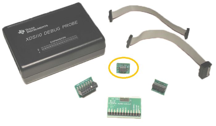
What connector do I need to put on my board to connect with the XDS110? The datasheet is vague, and the wiki doesn't specify if it is showing the connector on debugger, or the mate, or the connecting cable. The previous post of this question was not answered (though it is now locked).

  • Steve,

    On our boards we use p/n 3221-10-0300-00, which is the SMD version. That's usually available at Digikey.

    There is a "nicer" one, a bit more compact, but it was way more expensive everywhere we looked.

    Regards

    Bruno

  • Hi,

    Please check the reference below:
    software-dl.ti.com/.../emu_jtag_connectors.html

    Hope this helps,
    Rafael
  • Bruno,

    That is a 10-pin connector ... are you using the adapter for the Cortex-M 10-pin? If so, that one doesn't bring out the TRSTn signal, which I need.

    Thanks,

    Steve

  • Thanks, Rafael. That is similar to what is on the Wiki, but with the addition of useful info about the cable and target connectors.
  • Steve,

    I am glad that it helped. The page I sent before is the one actively maintained.

    Regards,
    Rafael
  • Hi Steve,

    We are not using adapters... We use that connector as the standard to program/debug TM4C targets in our boards.

    The #RST line is part of the pins, I'm not sure if that is the same as the denomination you are referring to... Our schematic and an image is available here:

    With that arrangement, it is possible to use an XDS110 as the debugging probe - and also, older XDS100, or commercial pods such as the XDS200.

    Regards

    Bruno

  • Your pinouts don't match the 10-pin adapter that comes with the XDS110, so I still have no idea how you connect. That isn't an XDS110 in the picture, so maybe we are talking about different things. On the other hand, the documentation is a bit lacking, so maybe I am just missing something. In any case, the link that Rafael posted above has the connectors I was looking for.
  • Steve,
    Now, that's even more confusing...
    The red board on my picture is an off-the-shelf CC2650 Launchpad. It has a "complimentary, free of charge" XDS110 on the upper part. It is not unusual for us to employ Launchpads like that when we need to program or debug our boards: we just remove the power jumper that goes to the CC2650 target MCU on the lower part of the board - and that "red thing" becomes a USB XDS110, ready to be used with Code Composer.
    The pinout in our schematic is the very same as it is found on the TI Launchpad (the gray flat cable on the image is 1 to 1).
    Not sure if that helps your particular application, but it is an easy and affordable way to let our colleagues develop firmware, program our boards , and do all usual tasks (including breakpoints, 50Hz variable updates, memory access and other features) that don't require extra fast or professional JTAG access such as XDS560 or JLinks...
    Regards
    Bruno

  • OK, that makes sense. Unfortunately, the actual XDS110 has a different connector (20-pins), and a slew of adapters that it comes with (including a 10-pin, but not that one).
    Thanks,
    Steve
  • Hi Steve,

    Just dug a big deeper into this. I checked TI's "actual" XDS110 manual on this document:

    www.ti.com/.../sprui94.pdf

    Conclusions:

    - Yes, our pinout shown above matches the XDS110 mapping, according to CM10 column on document entry 4.1.2

    - To use the board connector that I've shown on my first reply, the adapter that you will use (original on the XDS110 package) is the one in the middle on the picture below.

    The exact same situation applies if using, for example, an XDS200, like shown on the next image (same target board as the first picture I sent this morning).

    Hope this is of help.

    Cheers

    Bruno

  • Hi Bruno,
    That makes sense now, and I agree. I was thrown off by pin 3, which is shown as GND on the XDS110, but EXTDEBUG_ in your schematic (and makes sense now that I think about it). While I would much prefer to use the smaller 10-pin connector, I'm pretty sure I need access to the TRSTn signal. I am targeting a TMS320F28377D.
    Thanks,
    Steve
  • Hello again Steve,
    Thanks for the feedback. It is indeed all clear now! Another day, another lesson...
    If you do make your own custom adapter, you might still be able to use the smaller 10-pin header on your boards - note that free PIN#7 on the schematic, which can be routed to your TestResetNot signal...
    But this is just a blind suggestion, for I really have no experience on TMS320x, and can't be sure that other signals wouldn't be required...
    Regards
    Bruno