This thread has been locked.

If you have a related question, please click the "Ask a related question" button in the top right corner. The newly created question will be automatically linked to this question.

TM4C1294NCPDT: TM4C1294NCPDT

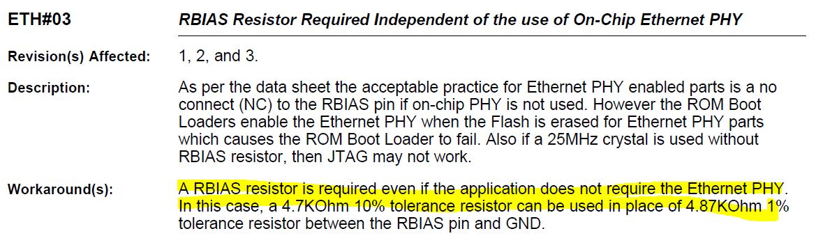
Part Number: TM4C1294NCPDT

We  designed a custom board based on TM4C1294NCPDT.  Connected the JTAG as per 14 pin connection ( section 4.1 of application note "Using TM4C12x Devices Over JTAG Interface").  I tried to flash the program through XDS 200 USB debugger from code composer.  Code composer throws the following error message

Error connecting to the target:
(Error -2062 @ 0x0)
Unable to halt device. Reset the device, and retry the operation. If error persists, confirm configuration, power-cycle the board, and/or try more reliable JTAG settings (e.g. lower TCLK).
(Emulation package 7.0.188.0)

When I tried to do Test connection, it pass the integrity check ( The JTAG DR Integrity scan-test has succeeded.).

Need help

  • Hi Ramesh,

     In section 6 of the app note "Using TM4C12x Devices Over JTAG Interface" there are some troubleshooting steps. I'm listing them here again. Please follow these steps to diagnose the connection issue. I will start with step 9. Do you have the RBIAS resistor populated as there is an errata related to this. Without the RBIAS resistor the JTAG connection may not wok even though the RBIAS resistor is for the PHY operation.

    If the JTAG IR and DR Integrity scan-test succeeds, it means that the device core is out of reset and may

    not have initialized itself. If, however, the integrity scan-test fails, the issue is in the power up process.

    The following steps must be followed to make sure every known cause is eliminated till the source of the

    issue is found:

    1. Check with a digital multi-meter that the VDD and VDDA supply rails are 3.3 V.

    (a) If not, then check the power supply aspect of the design.

    2. Check with a digital multi-meter that the VDDC rail is 1.2 V.

    (a) If not and providing a power from an external power source, make sure that the current limit is set

    around 150 mA.

    3. If the VDDC rail is at 1.2 V, make sure that the capacitance on the rail is as per the device-specific

    data sheet and the layout of the capacitors are as per the system design guidelines and application

    reports (see Section 8).

    4. Check whether the JTAG header is correctly mounted and the TDIS pin (if available) is connected to

    GND.

    5. Check on the JTAG header the VTREF pin is 3.3 V.

    6. Check whether the Reset Pin of the microcontroller is at 3.3 V.

    (a) If not, connect an external pull up.

    7. If using an external crystal oscillator, connect an oscilloscope on pin OSC0.

    (a) If the crystal is not oscillating, check the solder on the crystal and capacitors.

    (b) Always use the recommended crystals as per the device-specific data sheet.

    8. If not using an external crystal oscillator, make sure that the pin OSC0 is connected to GND.

    9. If using a TM4C129x device with integrated PHY, make sure that the RBIAS resistor is populated as

    per device-specific data sheet recommendation.

  • Hi Charles,
    Thanks for the reply. I have tried through all the troubleshooting steps and have no success. However we did not populate RBIAS resistor since we have not used Ethernet. I will try this tomorrow and let you know.

    Regards,
    Ramesh
  • Hi Charles,

    We populated the RBIAS resistor and I am able to flash now.  Thanks a lot for the support.

    Regards,

    Ramesh