This thread has been locked.

If you have a related question, please click the "Ask a related question" button in the top right corner. The newly created question will be automatically linked to this question.

CCS/TM4C1294NCPDT: Error in receiving CAN data

Part Number: TM4C1294NCPDT


Tool/software: Code Composer Studio

Hi,

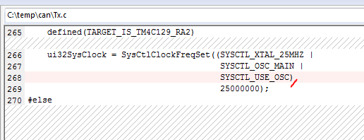
I am attempting to use the CAN bus on my TM4C1294XL. I started with the simple Rx and Tx codes and changed it to use the CAN1 so that I could use the UART0 for monitoring data. I am using two MCP2551 as the transceivers with 120 ohm termination resistors with RS terminal grounded. When I attempt to transmit, I get an errors in both the controllers. I have attached  the register description of both Transmit and receive. The Rx interrupt occurs only when I connect the Tx m/c. As I understand, the Tx and Rx error counters have filled which causes the error. So i tried reducing the transmission rate to 100 Kbps, I have also tried the multiple Tx and multiple Rx and the results are the same. Please let me know what could be the issue. The files are attached for reference along with the register description of the m/c.

CAN Tx,Rx.zip

  • The problem might be that you are not setting the system clock frequency correctly. Line 268 of your tx.c is missing a comma (,). Unfortunately, this omission is straight from the example. Try adding the comma, recompiling and retesting. If that does not work, try to look at the CAN signals with an oscilloscope to verify you are running at the expected baud rate.


    It looks like the rx.c file is exactly the same as the tx.c file. Was that an issue in creating the .zip? The same issue may exist in your receive routine.

  • Hi Bob,

    Thank you your response.

    Sorry, the file mixup was an error from my end. The actual Rx file is attached.

    I have updated the code as you suggested but I still get the same error. I will check with the oscilloscope and let you know what I find.

    Thank you

    //*****************************************************************************
    //
    // simple_rx.c - Example demonstrating simple CAN message reception.
    //
    // Copyright (c) 2010-2016 Texas Instruments Incorporated.  All rights reserved.
    // Software License Agreement
    //
    //   Redistribution and use in source and binary forms, with or without
    //   modification, are permitted provided that the following conditions
    //   are met:
    //
    //   Redistributions of source code must retain the above copyright
    //   notice, this list of conditions and the following disclaimer.
    //
    //   Redistributions in binary form must reproduce the above copyright
    //   notice, this list of conditions and the following disclaimer in the
    //   documentation and/or other materials provided with the
    //   distribution.
    //
    //   Neither the name of Texas Instruments Incorporated nor the names of
    //   its contributors may be used to endorse or promote products derived
    //   from this software without specific prior written permission.
    //
    // THIS SOFTWARE IS PROVIDED BY THE COPYRIGHT HOLDERS AND CONTRIBUTORS
    // "AS IS" AND ANY EXPRESS OR IMPLIED WARRANTIES, INCLUDING, BUT NOT
    // LIMITED TO, THE IMPLIED WARRANTIES OF MERCHANTABILITY AND FITNESS FOR
    // A PARTICULAR PURPOSE ARE DISCLAIMED. IN NO EVENT SHALL THE COPYRIGHT
    // OWNER OR CONTRIBUTORS BE LIABLE FOR ANY DIRECT, INDIRECT, INCIDENTAL,
    // SPECIAL, EXEMPLARY, OR CONSEQUENTIAL DAMAGES (INCLUDING, BUT NOT
    // LIMITED TO, PROCUREMENT OF SUBSTITUTE GOODS OR SERVICES; LOSS OF USE,
    // DATA, OR PROFITS; OR BUSINESS INTERRUPTION) HOWEVER CAUSED AND ON ANY
    // THEORY OF LIABILITY, WHETHER IN CONTRACT, STRICT LIABILITY, OR TORT
    // (INCLUDING NEGLIGENCE OR OTHERWISE) ARISING IN ANY WAY OUT OF THE USE
    // OF THIS SOFTWARE, EVEN IF ADVISED OF THE POSSIBILITY OF SUCH DAMAGE.
    //
    // This is part of revision 2.1.3.156 of the Tiva Firmware Development Package.
    //
    //*****************************************************************************
    
    #include <stdbool.h>
    #include <stdint.h>
    #include "inc/hw_can.h"
    #include "inc/hw_ints.h"
    #include "inc/hw_memmap.h"
    #include "inc/hw_types.h"
    #include "driverlib/can.h"
    #include "driverlib/gpio.h"
    #include "driverlib/interrupt.h"
    #include "driverlib/pin_map.h"
    #include "driverlib/sysctl.h"
    #include "driverlib/uart.h"
    #include "utils/uartstdio.h"
    
    //*****************************************************************************
    //
    //! \addtogroup can_examples_list
    //! <h1>Simple CAN RX (simple_rx)</h1>
    //!
    //! This example shows the basic setup of CAN in order to receive messages
    //! from the CAN bus.  The CAN peripheral is configured to receive messages
    //! with any CAN ID and then print the message contents to the console.
    //!
    //! This example uses the following peripherals and I/O signals.  You must
    //! review these and change as needed for your own board:
    //! - CAN1 peripheral
    //! - GPIO port B peripheral (for CAN1 pins)
    //! - CAN1RX - PB0
    //! - CAN1TX - PB1
    //!
    //! The following UART signals are configured only for displaying console
    //! messages for this example.  These are not required for operation of CAN.
    //! - GPIO port A peripheral (for UART0 pins)
    //! - UART0RX - PA0
    //! - UART0TX - PA1
    //!
    //! This example uses the following interrupt handlers.  To use this example
    //! in your own application you must add these interrupt handlers to your
    //! vector table.
    //! - INT_CAN1 - CANIntHandler
    //
    //*****************************************************************************
    
    //*****************************************************************************
    //
    // A counter that keeps track of the number of times the RX interrupt has
    // occurred, which should match the number of messages that were received.
    //
    //*****************************************************************************
    volatile uint32_t g_ui32MsgCount = 0;
    
    //*****************************************************************************
    //
    // A flag for the interrupt handler to indicate that a message was received.
    //
    //*****************************************************************************
    volatile bool g_bRXFlag = 0;
    
    //*****************************************************************************
    //
    // A flag to indicate that some reception error occurred.
    //
    //*****************************************************************************
    volatile bool g_bErrFlag = 0;
    
    //*****************************************************************************
    //
    // This function sets up UART0 to be used for a console to display information
    // as the example is running.
    //
    //*****************************************************************************
    void
    InitConsole(void)
    {
        //
        // Enable GPIO port A which is used for UART0 pins.
        // TODO: change this to whichever GPIO port you are using.
        //
        SysCtlPeripheralEnable(SYSCTL_PERIPH_GPIOA);
    
        //
        // Configure the pin muxing for UART0 functions on port A0 and A1.
        // This step is not necessary if your part does not support pin muxing.
        // TODO: change this to select the port/pin you are using.
        //
        GPIOPinConfigure(GPIO_PA0_U0RX);
        GPIOPinConfigure(GPIO_PA1_U0TX);
    
        //
        // Enable UART0 so that we can configure the clock.
        //
        SysCtlPeripheralEnable(SYSCTL_PERIPH_UART0);
    
        //
        // Use the internal 16MHz oscillator as the UART clock source.
        //
        UARTClockSourceSet(UART0_BASE, UART_CLOCK_PIOSC);
    
        //
        // Select the alternate (UART) function for these pins.
        // TODO: change this to select the port/pin you are using.
        //
        GPIOPinTypeUART(GPIO_PORTA_BASE, GPIO_PIN_0 | GPIO_PIN_1);
    
        //
        // Initialize the UART for console I/O.
        //
        UARTStdioConfig(0, 115200, 16000000);
    }
    
    //*****************************************************************************
    //
    // This function is the interrupt handler for the CAN peripheral.  It checks
    // for the cause of the interrupt, and maintains a count of all messages that
    // have been received.
    //
    //*****************************************************************************
    void
    CANIntHandler(void)
    {
        uint32_t ui32Status;
    
        //
        // Read the CAN interrupt status to find the cause of the interrupt
        //
        ui32Status = CANIntStatus(CAN1_BASE, CAN_INT_STS_CAUSE);
    
        //
        // If the cause is a controller status interrupt, then get the status
        //
        if(ui32Status == CAN_INT_INTID_STATUS)
        {
            //
            // Read the controller status.  This will return a field of status
            // error bits that can indicate various errors.  Error processing
            // is not done in this example for simplicity.  Refer to the
            // API documentation for details about the error status bits.
            // The act of reading this status will clear the interrupt.
            //
            ui32Status = CANStatusGet(CAN1_BASE, CAN_STS_CONTROL);
    
            //
            // Set a flag to indicate some errors may have occurred.
            //
            g_bErrFlag = 1;
        }
    
        //
        // Check if the cause is message object 1, which what we are using for
        // receiving messages.
        //
        else if(ui32Status == 1)
        {
            //
            // Getting to this point means that the RX interrupt occurred on
            // message object 1, and the message reception is complete.  Clear the
            // message object interrupt.
            //
            CANIntClear(CAN1_BASE, 1);
    
            //
            // Increment a counter to keep track of how many messages have been
            // received.  In a real application this could be used to set flags to
            // indicate when a message is received.
            //
            g_ui32MsgCount++;
    
            //
            // Set flag to indicate received message is pending.
            //
            g_bRXFlag = 1;
    
            //
            // Since a message was received, clear any error flags.
            //
            g_bErrFlag = 0;
        }
    
        //
        // Otherwise, something unexpected caused the interrupt.  This should
        // never happen.
        //
        else
        {
            //
            // Spurious interrupt handling can go here.
            //
        }
    }
    
    //*****************************************************************************
    //
    // Configure the CAN and enter a loop to receive CAN messages.
    //
    //*****************************************************************************
    int
    main(void)
    {
    #if defined(TARGET_IS_TM4C129_RA0) ||                                         \
        defined(TARGET_IS_TM4C129_RA1) ||                                         \
        defined(TARGET_IS_TM4C129_RA2)
        uint32_t ui32SysClock;
    #endif
    
        tCANMsgObject sCANMessage;
        uint8_t pui8MsgData[8];
    
        //
        // Set the clocking to run directly from the external crystal/oscillator.
        // TODO: The SYSCTL_XTAL_ value must be changed to match the value of the
        // crystal used on your board.
        //
    #if defined(TARGET_IS_TM4C129_RA0) ||                                         \
        defined(TARGET_IS_TM4C129_RA1) ||                                         \
        defined(TARGET_IS_TM4C129_RA2)
        ui32SysClock = SysCtlClockFreqSet((SYSCTL_XTAL_25MHZ |
                                           SYSCTL_OSC_MAIN |
                                           SYSCTL_USE_OSC),
                                           25000000);
    #else
        SysCtlClockSet(SYSCTL_SYSDIV_1 | SYSCTL_USE_OSC | SYSCTL_OSC_MAIN |
                       SYSCTL_XTAL_16MHZ);
    #endif
    
        //
        // Set up the serial console to use for displaying messages.  This is
        // just for this example program and is not needed for CAN operation.
        //
        InitConsole();
    
        //
        // For this example CAN1 is used with RX and TX pins on port B4 and B5.
        // The actual port and pins used may be different on your part, consult
        // the data sheet for more information.
        // GPIO port B needs to be enabled so these pins can be used.
        // TODO: change this to whichever GPIO port you are using
        //
        SysCtlPeripheralEnable(SYSCTL_PERIPH_GPIOB);
    
        //
        // Configure the GPIO pin muxing to select CAN1 functions for these pins.
        // This step selects which alternate function is available for these pins.
        // This is necessary if your part supports GPIO pin function muxing.
        // Consult the data sheet to see which functions are allocated per pin.
        // TODO: change this to select the port/pin you are using
        //
        GPIOPinConfigure(GPIO_PB0_CAN1RX);
        GPIOPinConfigure(GPIO_PB1_CAN1TX);
    
        //
        // Enable the alternate function on the GPIO pins.  The above step selects
        // which alternate function is available.  This step actually enables the
        // alternate function instead of GPIO for these pins.
        // TODO: change this to match the port/pin you are using
        //
        GPIOPinTypeCAN(GPIO_PORTB_BASE, GPIO_PIN_0 | GPIO_PIN_1);
    
        //
        // The GPIO port and pins have been set up for CAN.  The CAN peripheral
        // must be enabled.
        //
        SysCtlPeripheralEnable(SYSCTL_PERIPH_CAN1);
    
        //
        // Initialize the CAN controller
        //
        CANInit(CAN1_BASE);
    
        //
        // Set up the bit rate for the CAN bus.  This function sets up the CAN
        // bus timing for a nominal configuration.  You can achieve more control
        // over the CAN bus timing by using the function CANBitTimingSet() instead
        // of this one, if needed.
        // In this example, the CAN bus is set to 500 kHz.  In the function below,
        // the call to SysCtlClockGet() or ui32SysClock is used to determine the
        // clock rate that is used for clocking the CAN peripheral.  This can be
        // replaced with a  fixed value if you know the value of the system clock,
        // saving the extra function call.  For some parts, the CAN peripheral is
        // clocked by a fixed 8 MHz regardless of the system clock in which case
        // the call to SysCtlClockGet() or ui32SysClock should be replaced with
        // 8000000.  Consult the data sheet for more information about CAN
        // peripheral clocking.
        //
    #if defined(TARGET_IS_TM4C129_RA0) ||                                         \
        defined(TARGET_IS_TM4C129_RA1) ||                                         \
        defined(TARGET_IS_TM4C129_RA2)
        CANBitRateSet(CAN1_BASE, ui32SysClock, 500000);
    #else
        CANBitRateSet(CAN1_BASE, SysCtlClockGet(), 500000);
    #endif
    
        //
        // Enable interrupts on the CAN peripheral.  This example uses static
        // allocation of interrupt handlers which means the name of the handler
        // is in the vector table of startup code.  If you want to use dynamic
        // allocation of the vector table, then you must also call CANIntRegister()
        // here.
        //
        // CANIntRegister(CAN1_BASE, CANIntHandler); // if using dynamic vectors
        //
        CANIntEnable(CAN1_BASE, CAN_INT_MASTER | CAN_INT_ERROR | CAN_INT_STATUS);
    
        //
        // Enable the CAN interrupt on the processor (NVIC).
        //
        IntEnable(INT_CAN1);
    
        //
        // Enable the CAN for operation.
        //
        CANEnable(CAN1_BASE);
    
        //
        // Initialize a message object to be used for receiving CAN messages with
        // any CAN ID.  In order to receive any CAN ID, the ID and mask must both
        // be set to 0, and the ID filter enabled.
        //
        sCANMessage.ui32MsgID = 0;
        sCANMessage.ui32MsgIDMask = 0;
        sCANMessage.ui32Flags = MSG_OBJ_RX_INT_ENABLE | MSG_OBJ_USE_ID_FILTER;
        sCANMessage.ui32MsgLen = 4;
    
        //
        // Now load the message object into the CAN peripheral.  Once loaded the
        // CAN will receive any message on the bus, and an interrupt will occur.
        // Use message object 1 for receiving messages (this is not the same as
        // the CAN ID which can be any value in this example).
        //
        CANMessageSet(CAN1_BASE, 1, &sCANMessage, MSG_OBJ_TYPE_RX);
    
        //
        // Enter loop to process received messages.  This loop just checks a flag
        // that is set by the interrupt handler, and if set it reads out the
        // message and displays the contents.  This is not a robust method for
        // processing incoming CAN data and can only handle one messages at a time.
        // If many messages are being received close together, then some messages
        // may be dropped.  In a real application, some other method should be used
        // for queuing received messages in a way to ensure they are not lost.  You
        // can also make use of CAN FIFO mode which will allow messages to be
        // buffered before they are processed.
        //
    
        UARTprintf("Ready to start\n");
    
        for(;;)
        {
            unsigned int uIdx;
    
            //
            // If the flag is set, that means that the RX interrupt occurred and
            // there is a message ready to be read from the CAN
            //
            if(g_bRXFlag)
            {
                //
                // Reuse the same message object that was used earlier to configure
                // the CAN for receiving messages.  A buffer for storing the
                // received data must also be provided, so set the buffer pointer
                // within the message object.
                //
                sCANMessage.pui8MsgData = pui8MsgData;
    
                //
                // Read the message from the CAN.  Message object number 1 is used
                // (which is not the same thing as CAN ID).  The interrupt clearing
                // flag is not set because this interrupt was already cleared in
                // the interrupt handler.
                //
                CANMessageGet(CAN1_BASE, 1, &sCANMessage, 0);
    
                //
                // Clear the pending message flag so that the interrupt handler can
                // set it again when the next message arrives.
                //
                g_bRXFlag = 0;
    
                //
                // Check to see if there is an indication that some messages were
                // lost.
                //
                if(sCANMessage.ui32Flags & MSG_OBJ_DATA_LOST)
                {
                    UARTprintf("CAN message loss detected\n");
                }
    
                //
                // Print out the contents of the message that was received.
                //
                UARTprintf("Msg ID=0x%08X len=%u data=0x",
                           sCANMessage.ui32MsgID, sCANMessage.ui32MsgLen);
                for(uIdx = 0; uIdx < sCANMessage.ui32MsgLen; uIdx++)
                {
                    UARTprintf("%02X ", pui8MsgData[uIdx]);
                }
                UARTprintf("total count=%u\n", g_ui32MsgCount);
            }
        }
    
        //
        // Return no errors
        //
        return(0);
    }
    

  • Bob Crosby said:
    Unfortunately, this omission (missing comma) is straight from the example.

    That's no good - yet somehow my firm - using 'Simple_Rx.c & Simple_Tx.c'  (under (past) StellarisWare) - for the basis for our CAN Apps - has escaped such issue!     And we note - no such 'TM4C129' existed (requiring that entirely new/deviating System Frequency command) - under that (past) regime.   

    Is it not clear that 'BETTER ALERTING' of such (missing comma) IS Required - to save User-Clients - from this 'known' shortcoming?    

    That's NOT your JOB - yet marching users - atop so high (and unprotected) 'Cliff'  - proves 'Not so wise.'       No one here 'expects vendor perfection.'      Yet some - effective correction (or at least - (some) warning) seems far superior to ... avoidance!

  • I tried to monitor the data on the oscilloscope. I have changed my identified to 29 ( 0x1D) and my data packet as 45 (2D).

    If I understand right, the time quantum (tq) = BRP / fsys = 63 / 16,000,000 = 3.9375 usec.

    The total BIT time = [TSEG1 + TSEG2 + 3] × t q = 74.8 usec.

    The data frame should be [SOF, 11-bit identifier, ...........] = [0 00000011101..........]. Thus the bus should drop to recessive state after 7 x 74.8 usec = 523.6 usec.

    However, the dominant state lasts for 2200 usec as observed from the oscilloscope and starts over.  When no acknowledgement is received? (I presume).

    Please correct me if I am wrong.

     I have checked the register values and they seem to be fine.  Is there something wrong in the setup of the transmitter or something I have missed.

    Thank you

  • Tarun Bajaj said:
    I started with the simple Rx and Tx codes ... and (then) changed it...

    Does your (past) success w/'Simple_Rx & Simple_Tx' - not  warrant your revisit  of  those key files?     

    By so doing - you may, 'COMPARE & CONTRAST' a 'Proven Successful' CAN Implementation - against  'that which you now have'  - which is failing.    Close examination of the various 'Set-Ups & Configs - along w/"Simple_Rx/Tx' Operational Scope Caps' - are extremely likely to provide "Key Facts'  -  which may 'drive you  onward' - toward  CAN Success...

    As always - many would urge your use of  'KISS'  - you appear to have made MANY Changes - thus a proper  'identification of FAULT'  is ' FAR MORE DIFFICULT' ... AND ... 'TIME CONSUMING!'    Neither Good!    

    'KISS' instead - due to its tightly controlled, systematic nature - would direct,  'ONE Simple (Measurable Change at a time) Always Tested & Verified!'     Failure then (even 'slight' deviations -are FAR MORE NOTABLE  (and more quickly & easily)  DETECTED - which enables  'MUCH FASTER/EASIER'  FIXES!!

    The superior Control & Insights - provided (only) by 'KISS'  surely yields a  'vastly superior method' - does it not?

  • I found the problem!

    Its is to do with the fact that I am using GNU compiler. The same set of codes work on TI compiler.

    I have to use GNU compiler, is there anything I do to fix the issue?

    Thank you.

  • My friend - do you not - once again - attempt the  'unnecessarily difficult/complicating' task of,   'TOO LARGE A CHALLENGE?'

    Would not your 'Adoption of  'KISS' - best enable you to, 'Test/Verify' key (yet vastly size limited) segments of your GNU compiler - so that you may 'PRECISELY IDENTIFY'  just when/where - GNU & Vendor's compiler differ?     Note too - even 'slowed & impeded'  by your  'All in One' approach' - you've been able to  (nearly) identify the (likely) area of  'failure.'

    'KISS' directs that you 'Laser Focus' upon that (limited)  currently failing area  - and 'A-B - Compare/Contrast'  - between 'working & failing' compiler outputs.     That 'KISS method' - proves the  'fastest, easiest & most probable PATH'  to your (and of course, others') success - both here (now) ... and  LONG INTO  your/their FUTURE!    

    Note too - that by performing such 'detailed examination' - you are likely  to discover the exact cause - and armed w/that key (new) knowledge  -  effectively  'guard against' - any future,  'Revisits of this and/or similar  issues!'       That's just HUGE  -  'KISS' (really/clearly ) deserves  your adoption...

  • Thanks cb1_mobile,

    That did work!

    It was a silly error from my end. The #if function was not applied in the case of GCC compiler as it was missing the required definitions. As a result, the registers were incorrectly configured.

    This solved the issue partly. In am able to transmit data and can monitor that on my oscilloscope. However, the receiver with all the same changes always gives the id and data, both as '0000s' for any value being transmitted.

    I see that others have faced the issue but was unable to find the solution. Kindly let me know how I can proceed.

  • Tarun Bajaj said:
    I am able to transmit data and can monitor that on my oscilloscope.

    Does your, 'monitoring' of that transmit data - extend to your being able to 'read it?     KISS - once again - comes to your rescue by suggesting your (acquisition) of an 'independent' CAN bus monitor.    (this may even be available as a 'PC' program w/CAN to PC signal interface.)

    Your issue may result from your 'reading 'DIRTY DATA'  (not the most current) - and such, 'Second Set of Diagnostic EYES' can (best) confirm that.

    And again - when all else fails - you may revert back to simple_can_RX/TX - and carefully note - what proper data appears as - and 'when, where & how' - it is received.

    One (more)  tip - you may be able to 'best recognize' your transmitted data (while 'on the CAN Bus') by employing (either) 0X55 or 0XAA - as both produce an 'Alternating Bit Pattern' - greatly easing/aiding visual recognition.      (even when - especially when - the correct diagnostic equipment - proves unavailable...)