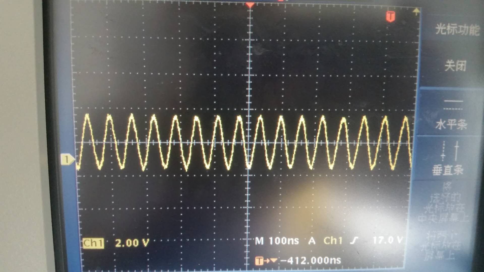
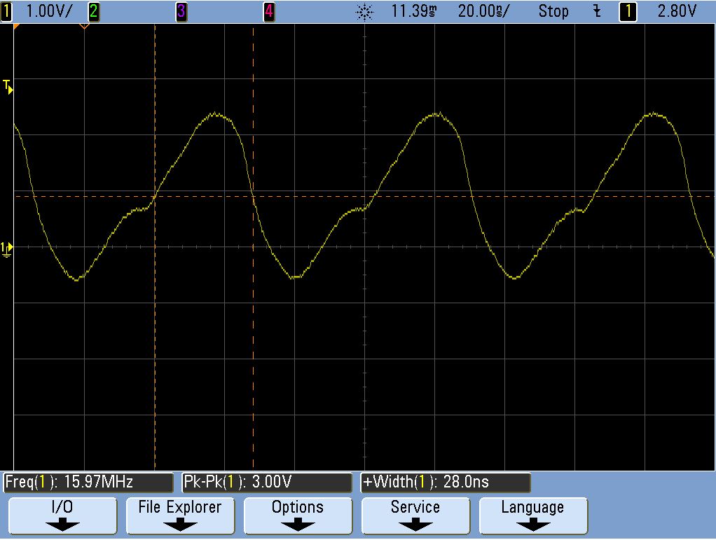
We capture the similar waveform for XOSC1 pin on both Customer Board and TI LanuchPad as below, Customer ask what is the reason for the waveform is not pure sine-wave? What MCU performance it will affect?
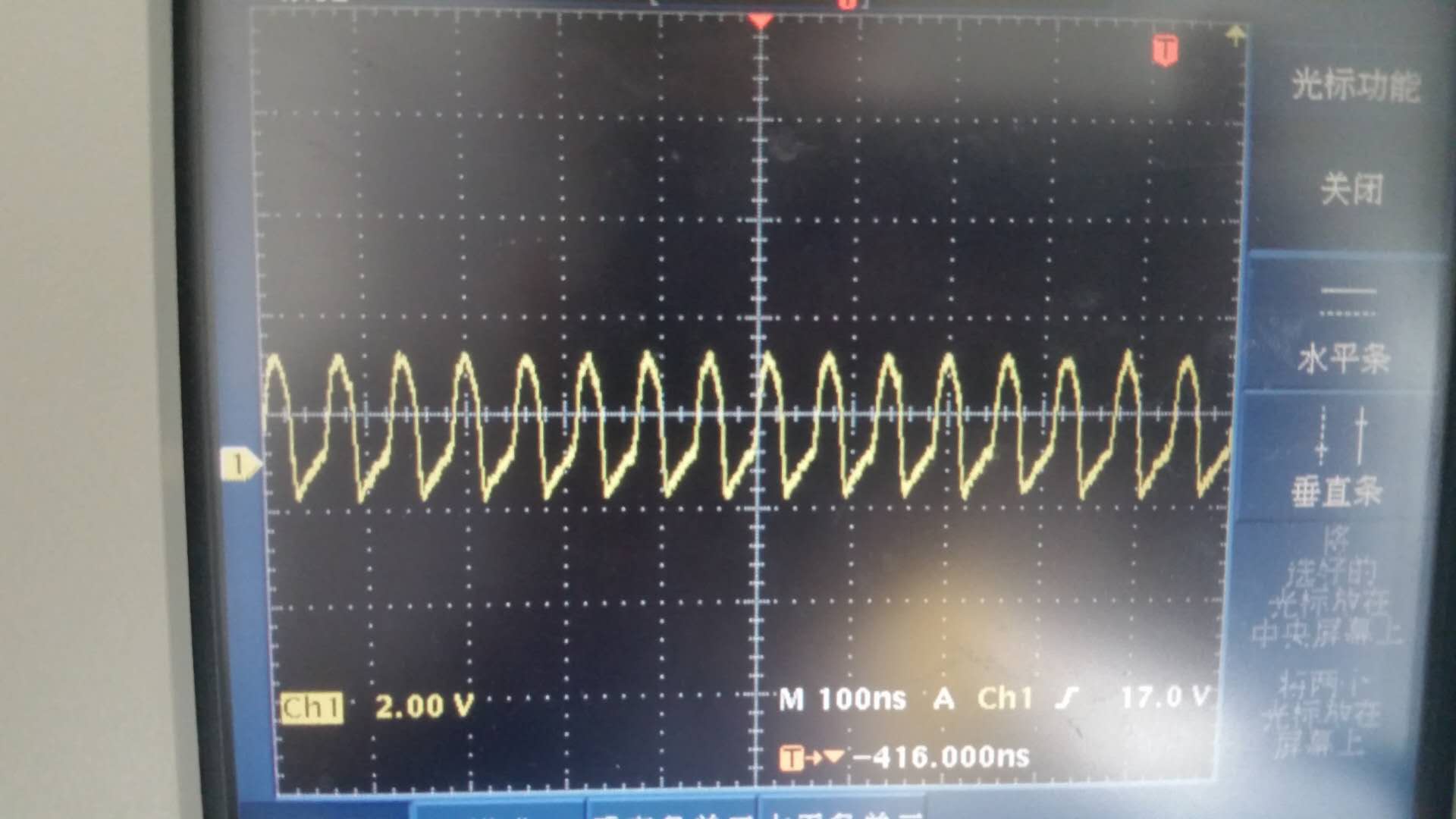
We capture the similar waveform for XOSC1 pin on both Customer Board and TI LanuchPad as below, Customer ask what is the reason for the waveform is not pure sine-wave? What MCU performance it will affect?