Part Number: LM3S9D96
Hello,
In our product, a few Microcontroller (LM3S9D96) is not work when did cold reset.
This issue only occurred cold reset for 2000ms.
We investigate the cause of this issue.
Could you please let me know if you have heard about this phenomenon?
How to reproduce:
- To start Microcontroller (supply 3.3V). -> work well
- Power off during 2000ms (stop to supply).
- Restart Microcontroller (supply 3.3V). -> not work
Our investigate:
- This issue don't occurred if the step.2 change to less than 1000ms or over 5000ms.
- It is work well when warm the microcontroller, even if step.2 is 2000ms.
- Below images is signal wave on failed microcontroller.
Condition:
- Microcontrollers is written mini-loader which initialize hardware and start functional software from persistent storage.
- ocontroller is connected SDRAM, Flash, EEPROM and other.
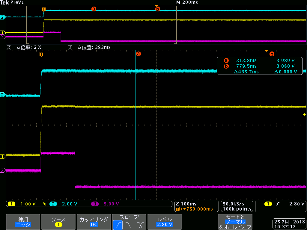
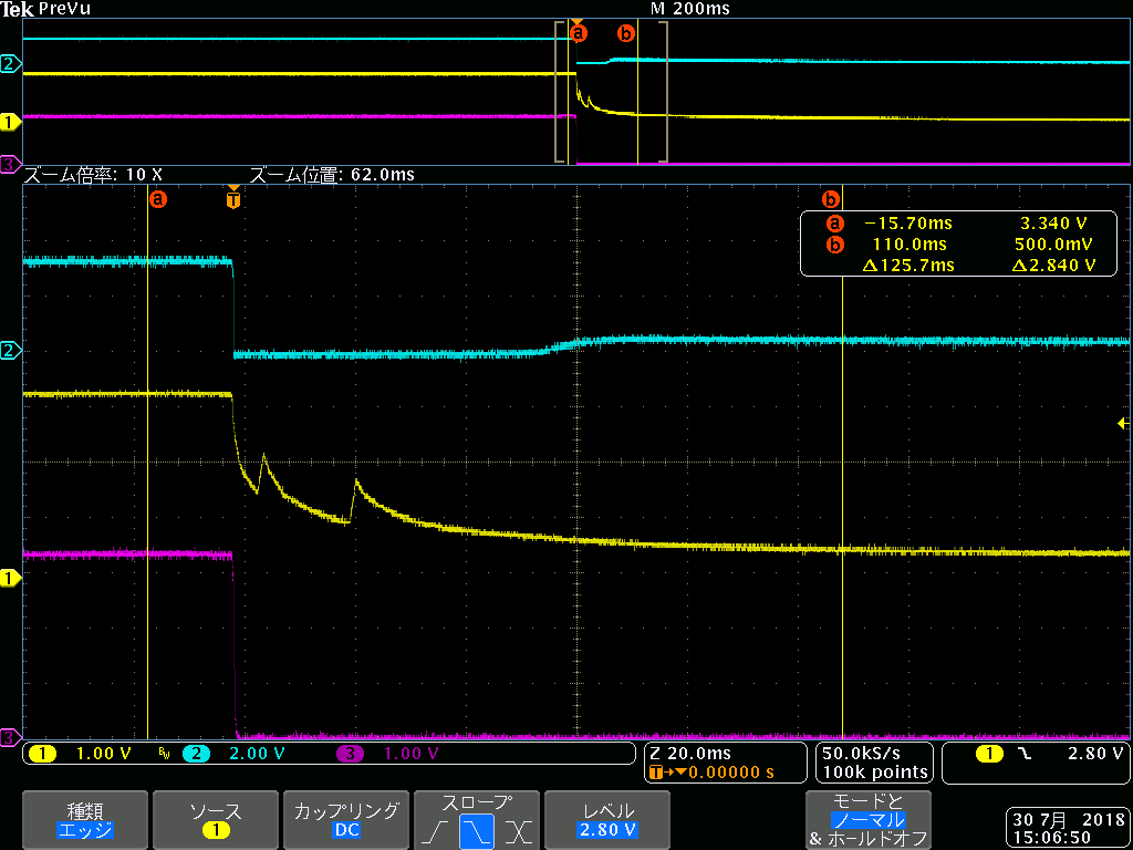
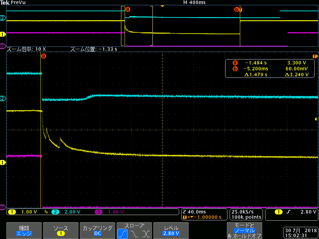
Failed pattern: power off for 2000ms
1 (yellow) is 3.3V supply to VDD.
2 (blue) is Reset~ signal on RST~.
3 (magenta) is serial message (RS232) from PA1/U0TX.
Step.2 power off
Step.3 restart
-> Microcontroller don't output serial message after restart.
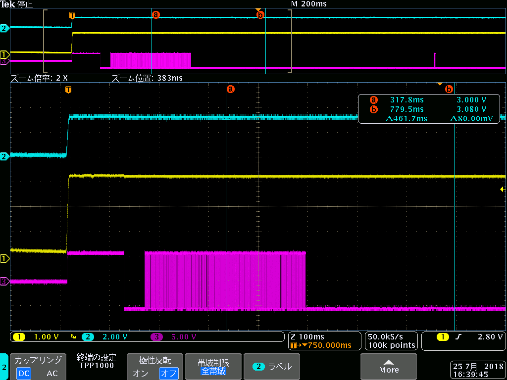
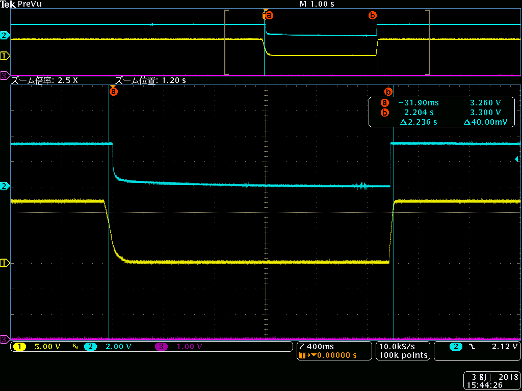
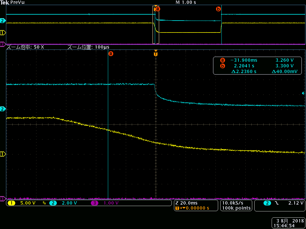
Succeed pattern : power off for 1000ms
1 (yellow) is 3.3V supply to VDD.
2 (blue) is Reset~ signal on RST~.
3 (magenta) is serial message (RS232) from PA1/U0TX.
Step.2 power off
Step.3 restart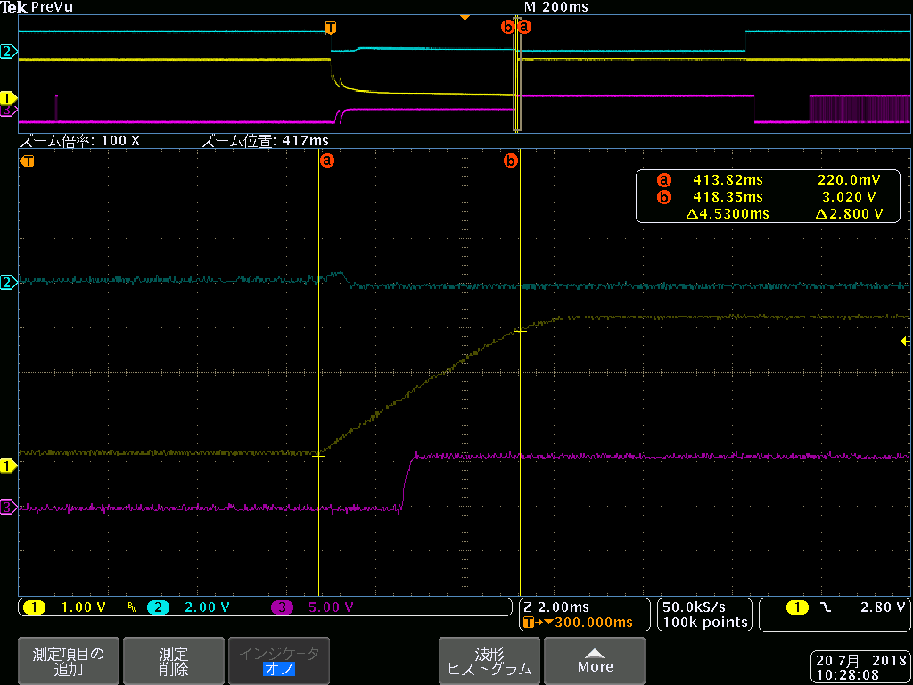

-> Microcontroller start to output serial message after 660ms from restart.
Best Regards.