This thread has been locked.

If you have a related question, please click the "Ask a related question" button in the top right corner. The newly created question will be automatically linked to this question.

TPS3305-18

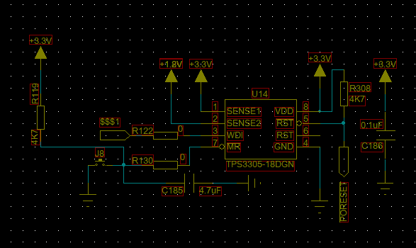
As you see above ,Now I have a problem。 When I press the reset button, the tps3305-18 output does not respond. What could be the cause of this problem? I measure The power quality of 3.3V and 1.8V are all very good。  And the WDI input is High resistance state。

  • hello,is there anyone WHO can give me some advice?
  • user4973896 said:
    is there anyone WHO can give me some advice?

    Feel your pain - yet might not (much) of that (pain) be 'self-inflicted?'

    As for your advice request - kindly note:

    • this forum focuses upon the TM4C family of MCUs   (your arrival here remains a 'mystery' - your TPS device appears to be a voltage monitor)   [yet possibly - an MCU Supervisor - and that - if true - deserved mention]
    • no link was provided to your device - such is (usually) required.   ('lessens the burden' upon your 'would-be' helper crüe - who have (other) items on their agenda)
    • I looked hard at your schematic (appears to be PCad) and believe that 'POReset' is the device's output pin.       That should have been explained...    Looking further - I now note that (both) RST & /RST - may serve as outputs
    • you do not note 'just how' you've determined that "Output" fails.    Could 'output' be a 'pulse' - which is brief & not sustained?     (thus passes un-noted - unless  you've a scope set to capture/view - 'very brief events!')     A DMM is most 'unlikely' to 'note' a short-duration pulse!
    • I doubt that pin 'WDI' should 'float.'     (you note - high resistance)    Most always - device input pins should be tied to VDD or VSS - most safely-done via pull-up/down resistors - tied to a supply rail.   (VDD or VSS)
    • it is always wise to provide more detail (i.e. some detail) as regards the device's 'purpose.'    Not always do posters choose the 'best/most appropriate device' -  superior device recommendations may be provided - but (only) when such 'purpose info' IS included
  • Hello,

    The problem is most likely caused by R130. Since the /MR pin is internally pulled up to VDD via a pull-up resistor, when you press the reset button at /MR, R130 acts as the bottom resistor of a resistor divider with the top resistor internal to the device. If you short R130, this ensures that a button press will in fact pull /MR to GND potential which will meet the VIL requirement provided in the specs table of the datasheet.

    Please provide feedback if this fix works for solving your issue. Thanks!

    -Michael

  • Michael DeSando1 said:
    If you short R130, this ensures that a button press will in fact pull /MR to GND potential

    Poster's schematic reveals 'R130' as 0Ω - clearly - it is (already) shorted!      Thus - the (diagnosis) - 'Shorting the 0Ω (R130)' appears (pardon)  'without merit.'      There is an external pull-up - fed to the switch side of R130 - which based upon vendor's commentary ('internally pulled up') appears superfluous.

    Poster notes WDI as 'high resistance' - which as the 'very first diagnostic response noted'  - (may) indicate 'floating' - which is most always - NOT good!     And indeed - device's datasheet orders pin 'WDI' to be regularly pulsed.   (i.e. w/in 1.6S)    (it may also (maybe) be held high - such was 'not revealed' by a serious read/review of the datasheet!)

    Often - when 'fine detail' is required ... it proves necessary to 'RTFM' - and in so doing - the following reveals:

    Thus - as the above reveals:

    • the earlier (first diagnostic posting) correctly surmised that the /Reset Output was a 'Pulse'  (200mS in duration) - which may be 'missed' if (only) a DMM serves as 'output monitor.'    That said - if pin /MR is held low - for a prolonged period - then the output will extend - to equal the time that /MR is active - plus the 200mS 'pulse time.'   (thus accommodating - DMM monitoring.)
    • the (unclear) high resistance of the 'WDI pin' - if floating - is improper.   In addition - the datasheet states only that  'signal transitions' must arrive - to prevent the Reset from being active.   (at minimum - convention would dictate that pin WDI be 'pulled up' - should a 'ready source' of 'signal transitions' - not yet - be available.   (which appears the case - here)    May it be noted that vendor's timing diagram (technical term follows) 'stinks' - as it reveals only the device's response to a prolonged 'low logic level' - which may suggest that a 'high logic level' (may) escape the dreaded Reset!

    In light of the above - it may just prove of (some) value - for follow on 'diagnostic posters' - to read/review - that earlier submitted.     (even by 'outsiders' - especially when such submission is 'high' in detail...)

  • Hello,

    Does this item still require additional support? Please provide a oscilloscope capture showing the SENSE pins, /MR, and RESET. This will help us to better understand the issue. Thanks!

    -Michael
  • Perhaps better if you address the poster - I've merely attempted to provide diagnostic guidance.
    Note too - that poster's 'Sense' pin WAS PROVIDED! (labeled on his scope-caps as VDD!)
    The advice to, 'Short R130' (continues) to provide (little) value - as poster's schematic reveals R130 as 0Ω...