Other Parts Discussed in Thread: EK-TM4C129EXL
Tool/software: TI-RTOS
Hi Ralph,
I am trying to interface EK-TM4C129EXL with the 8*8 LED module to display some characters. When I try to send 0x00 (Value - 0) through SPI the LED's in the display module should not glow, but it glows. I am not able to find why tose led glows.. Here is the code
/* XDCtools Header files */
#include <xdc/std.h>
#include <xdc/runtime/System.h>
#include <xdc/runtime/Error.h>

/* BIOS Header files */
#include <ti/sysbios/BIOS.h>
#include <ti/sysbios/knl/Semaphore.h>

/* TI-RTOS Header files */
#include <ti/drivers/GPIO.h>
#include <xdc/runtime/System.h>
//#include <xdc/cfg/global.h>

/* BIOS Header files */
#include <ti/sysbios/knl/Task.h>

/* TI-RTOS Header files */
#include <ti/drivers/GPIO.h>
#include <ti/drivers/SPI.h>
#include <ti/sysbios/BIOS.h>


#include <stdint.h>
#include <stdbool.h>
#include "inc/hw_types.h"
#include "inc/hw_memmap.h"
#include "driverlib/sysctl.h"
#include "driverlib/gpio.h"


#define TASKSTACKSIZE 1024
Task_Struct task0Struct;
Char task0Stack[TASKSTACKSIZE];

void spiDataSend();
void multiplexing();

volatile int rowSelect = 0;
volatile int count = 0;
extern Semaphore_Handle sem1;
extern Semaphore_Handle sem2;

UChar transmitBuffer[1] = {0x00};

/* Board Header file */
#include "Board.h"

void timerFunc()
{
    //static int count = 0;
    if (count++ & 1) {
        Semaphore_post(sem2);
    }
    else {
        Semaphore_post(sem1);
    }
}

/*Task1 is in a loop pending on sem1*/

tsk1Func(UArg arg0, UArg arg1)
{
    //GPIO_toggle(Board_LED1);
    while (1) {
    Semaphore_pend(sem1, BIOS_WAIT_FOREVER);
    multiplexing();
    /* task1 work here */

    }
}
/*Task2 is in a loop pending on sem2*/

tsk2Func(UArg arg0, UArg arg1)
{
    //GPIO_toggle(Board_LED0);
    while (1) {
    Semaphore_pend(sem2, BIOS_WAIT_FOREVER);
    spiDataSend();
     /* task2 work here */

   }
}


void spiDataSend()
{

    SPI_Handle spi;
    SPI_Params spiParams;
    SPI_Params_init(&spiParams);
    spiParams.dataSize = 1; /* dataSize can range from 4 to 8 bits */
    spiParams.transferMode = SPI_MODE_BLOCKING;
    spiParams.mode = SPI_MASTER;
    spiParams.bitRate = 2000000;
    spiParams.transferCallbackFxn = NULL;
    spi = SPI_open(Board_SPI0, &spiParams);
    if (spi == NULL) {
    /* Error opening SPI */
    }
    SPI_Transaction spiTransaction;
    spiTransaction.count = 8;
    spiTransaction.txBuf =  transmitBuffer;
    spiTransaction.rxBuf =  NULL;
    SPI_transfer(spi, &spiTransaction);
    SPI_close(spi);
}


void multiplexing()
{

    GPIOPinWrite(GPIO_PORTD_BASE, GPIO_PIN_0 , 1);  // LED Driver part of code this part works fine...
    GPIOPinWrite(GPIO_PORTD_BASE, GPIO_PIN_2 , 1);
    GPIOPinWrite(GPIO_PORTD_BASE, GPIO_PIN_0 , 0);
    GPIOPinWrite(GPIO_PORTE_BASE, (GPIO_PIN_0|GPIO_PIN_1) , rowSelect);
    GPIOPinWrite(GPIO_PORTD_BASE, GPIO_PIN_2 , 0);
    rowSelect++;
    if (rowSelect > 3)
    {
      rowSelect = 0;
    }

}


/*
 *  ======== main ========
 */
int main(void)
{
    /* Call board init functions */
    Board_initGeneral();
    Board_initGPIO();
    Board_initSPI();

    GPIOPinTypeGPIOOutput(GPIO_PORTE_BASE, (GPIO_PIN_0|GPIO_PIN_1)); // Initializing the Decoder part
    GPIOPinTypeGPIOOutput(GPIO_PORTD_BASE,(GPIO_PIN_0|GPIO_PIN_1|GPIO_PIN_2|GPIO_PIN_3)); // Initializing the SPI Driver part

    SysCtlPeripheralEnable(SYSCTL_PERIPH_GPIOE);
    while(!SysCtlPeripheralReady(SYSCTL_PERIPH_GPIOE))
    {
    }

    Task_Params taskParams;
    Task_Params_init(&taskParams);
    taskParams.priority = 2;
    taskParams.stackSize = TASKSTACKSIZE;
    taskParams.stack = &task0Stack;
    Task_construct(&task0Struct, (Task_FuncPtr)spiDataSend, &taskParams, NULL);
    /* Start BIOS */
    BIOS_start();
    return (0);
}
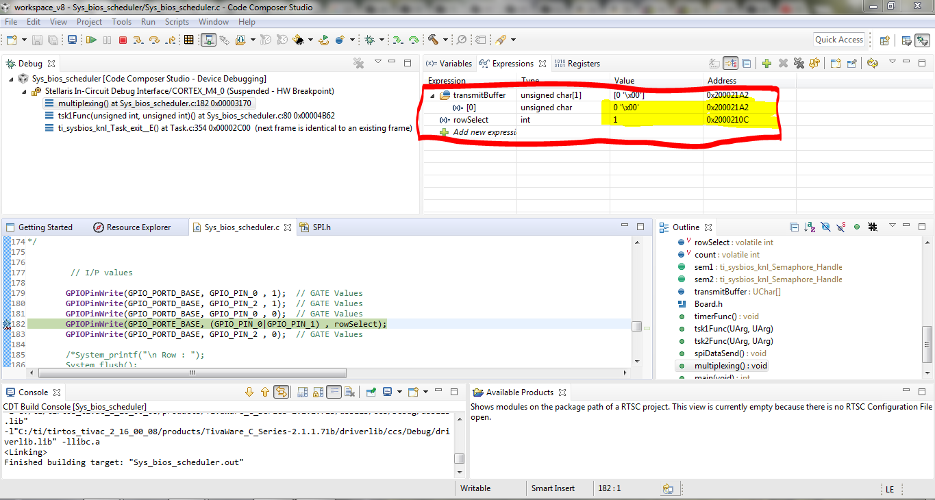
You can notice that the value in the tranmitbuffer is 0x00 Still the LED glows....
I am having certain doubts,
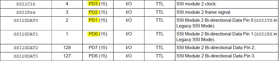
spi = SPI_open(Board_SPI0, &spiParams);
----> Do Board_SPI0 open the SPI on PORTD ???

 ----> In which register the value in the transmit buffer will be writeen ???

 ----> I can't able to see data value in SSI_DR_DATA - SSI Receive/Transmit Data