This thread has been locked.

If you have a related question, please click the "Ask a related question" button in the top right corner. The newly created question will be automatically linked to this question.

Frequency Doubler

Hi Guys,

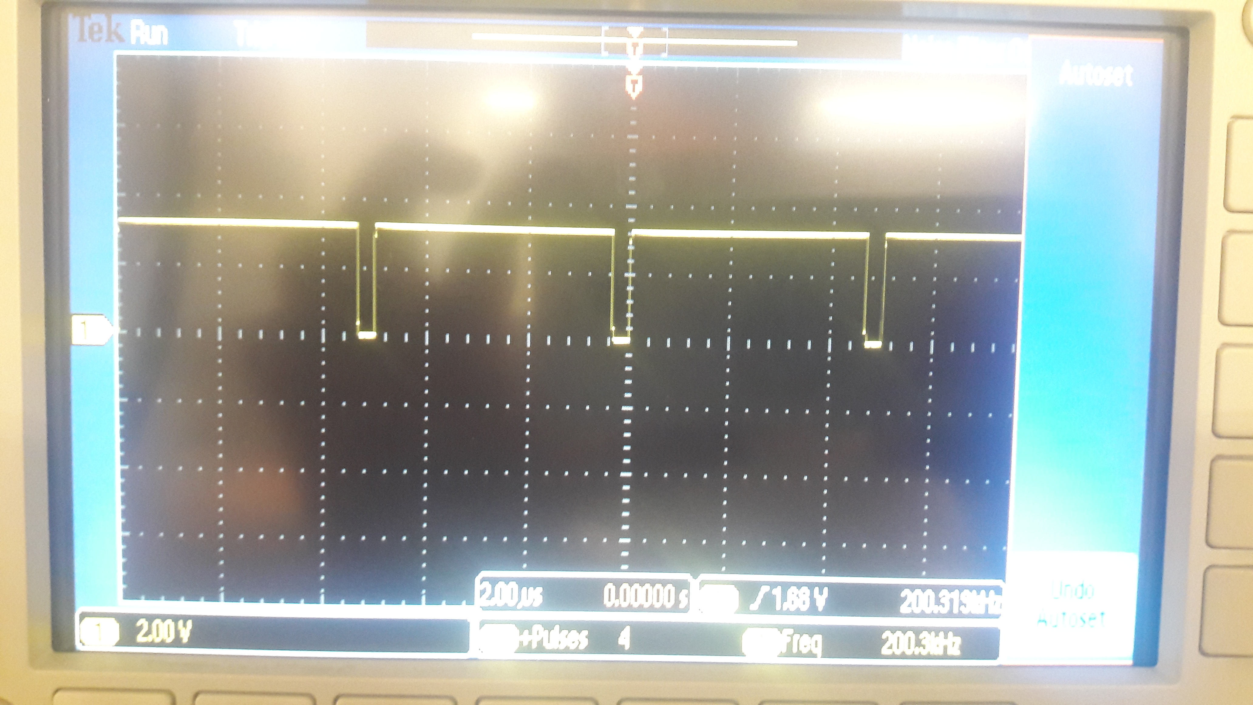
I have a 4V TTL signal operating at 200 kHz frequency(Input Signal can be seen in the figure attached) , i want to change its frequency to 400 Khz keeping the Voltage and waveform  almost the same there can be a little change but not too much.

So kindly suggest how can i do this please also include the IC number which i can use and how to use that IC.

Thanks.

  • Muhammad Javaid said:
    ... I want to change signal's frequency (double it)

    This is among 'classic' design implementations - dating to 'Pre-MCU' era.    A combination of 'ICs' were usually employed: one able to detect 'each signal edge' (led directly to the freq. doubling) and one or more additionally to render the (usual) combinatorial output.

    Muhammad Javaid said:
    include the IC number which i can use and how to use that IC.

    As this is an 'MCU-Centric' forum - is it not reasonable to believe that by 'IC' - you (really) intended MCU?

    If or when - employing an MCU - to meet this 'Frequency Doubler' role:

    • uniquely detect - and respond - to 'each' signal edge
    • MCU's Timer - commanded into 'One-Shot' mode (possibly 2 such Timers) directly or indirectly generates output - which follows (each/every) signal edge
    • the 'rising edge' (the second) such output must 'await' the conclusion of the 'falling edge's' (the first) newly created output.   (and then & only then - generate its output)

    KISS dictates that MCU programming is (vastly) 'Speeded, Eased (yet NOT Enhanced)' by the use of various added (external to the MCU) ICs - which 'gate' and/or delay and/or generate - such outputs...

    Management of those 'fine details' - and your clarification of  your intent regarding 'IC'  (was MCU intended?) deserve (some) thought/focused effort ... from the poster - don't you agree?

  • Can you suggest how to resolve my issue then ? Because i do not understand what you have said i am not an expert i am a beginner student so kindly be more specific and detailed.

    Thanks.
  • Have you truly done a 'focused read' of my writing?     (A 2nd read - especially noting those THREE Bullet Points - AND the UNANSWERED QUESTION (which surely - you CAN understand) seems highly indicated.

  • Yes i meant an MCU, but which MCU do i use which can accept this type of signal ?
  • Almost, 'Any MCU known to man' - can function adequately to your purpose! Your acquisition of vendor's TM4C123 'LaunchPad' should be 'well able' to meet your intention.    (and is a very fairly priced (low-cost) vendor offering)

    You would greatly increase your understanding by 'Drawing a Waveform' which displays your 'Newly Created Pulse Train' directly beneath (and aligned with) your 200KHz  signal.    (back of envelope - hand-drawn - then scanned and presented here - proves acceptable).     That drawing should 'better' enable your focus - and understanding - of how TWO PULSES are generated - based upon the arrival of 'just ONE' (that existing 200KHz signal.)

    After that drawings been created - your 'return' to the 3 bullet points - earlier presented - should prove 'easier for your grasp.'

    ***  For (very) Extra Credit ...  Students should 'Raise the Challenge' (slightly) from a, 'Known - Fixed Frequency (200KHz here) to a frequency which may 'HOP' (shift in Freq. - by (let's say) 10-50KHz (max) - from the current frequency input!)    

    What code changes - and/or external ICs - would best accommodate that - FAR MORE VALUABLE - 'GENERAL SOLUTION'S'  IMPLEMENTATION!     (i.e.  The MCU is enabled to automatically 'Detect the Input Frequency'  - and then produce  'Frequency Output' @ 2-5X  (as ordered or desired) -  that of the (input) frequency.)     THAT - would be a 'more reasonable'  homework assignment - would it not?    (w/adequate notice - & reward - staff here (may) be available - to 'Slay such homework dragons'...)

  • Thanks for your help. Again can i ask, when i run the code on this mcu once, after that can i disconnect it from the computer and only operate it using an external 5 v voltage supply ?
  • Muhammad Javaid said:
    Again can i ask, when i run the code on this mcu once, after that can i disconnect it from the computer and only operate it using an external 5 v voltage supply ?

    Absolutely YES - provided you 'properly' program the MCU.    Once programmed - you may 'free' the MCU from (any) connection to a PC - and observe your 'board's (continued, proper) response' - to your input signal.

    Do note - your use of 'Again' - proves suspect.    'Again' suggests that you've (earlier) made such a request!    No such (past) request (re: computer disconnect) was (anywhere) noted - thus 'again' proves improper.

    Your use of 'KISS' - to break your challenge into its smallest - constituent parts (which vastly speeds & eases your solution) - then test & confirm each - is your (and ALL others) fastest (and easiest) 'Path to Project Success.'

    Your creation of an appropriate 'timing diagram' - showing your NEW SIGNAL (F(out) = 2X F(in)) will surely ease your process.    (and that is 'Now, legitimately'  AGAIN  mentioned...)