This thread has been locked.

If you have a related question, please click the "Ask a related question" button in the top right corner. The newly created question will be automatically linked to this question.

TM4C1294NCPDT: Is this a valid concern regarding the backup battery?

Part Number: TM4C1294NCPDT

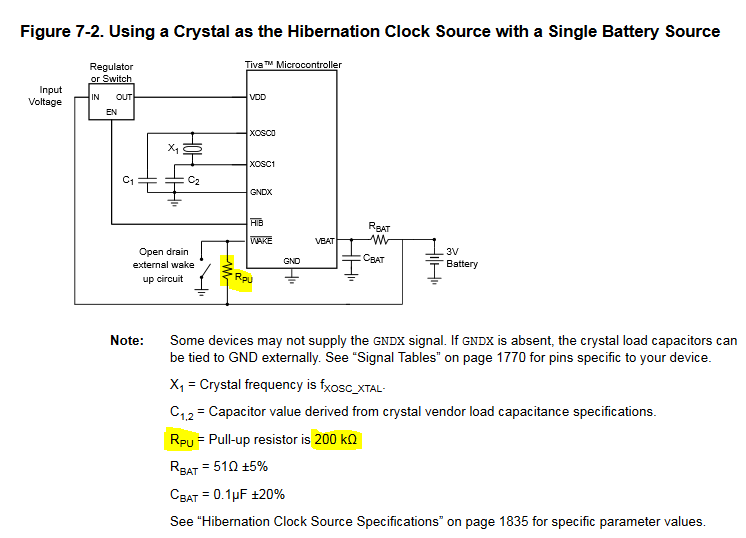
In my previous question regarding powering RTC of TM4C1294, Bob suggested the following circuit:

http://e2e.ti.com/cfs-file/__key/communityserver-discussions-components-files/908/3660.Capture.PNG

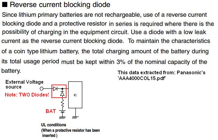
shouldn't it be better like this?

This will prevent the battery from powering other part of the circuit, also it puts some limit on the current the 3.3V may try to "charge" the battery when external power is provided (Not sure if a non-rechargeable battery lie CR2032 will be OK with this current when it is finally drained out)

  • David Chance said:
    Not sure if a non-rechargeable battery (i.e. CR2032) will be OK with this current when it is finally drained out)

    What if you 'gained knowledge'  that:

    • focusing such concern upon (only) 'finally drained out' was too restrictive?
    • we've just measured (moments ago) 10 or more (new) CR2032s - both Panasonic & Maxell - in no case was the initial (lightly loaded) voltage less than 3.25VDC!
    • might (even) your Schottky diode - and a 'slightly low'  (3V3/VCC) Regulator - produce a voltage 'LESS THAN' the CR2032?     What then - as the CR2032 assumes (always on) status?

    One of our firm's members is familiar w/the (potential 'charge aspects') of such 'coin-cell' batteries.    (She's back Monday)

    In light of these facts - It's believed that a (superior)  'switch-over circuit'  deserves your consideration - is that not (now) true?

  • Thank you for taking time to measure the batteries!

    I have only a few of Panasonic CR-2032s bought from digikey, and they all measure 3V only
  • David Chance said:
    I have only a few of Panasonic CR-2032s bought from digikey, and they all measure 3V only

    Unknown is the 'Shelf Time' (that time those batteries spent on digikey's shelves - and later - on yours.)      And - as I past wrote to you - our Li-Ion Batteries (primarily 'Name-brand'  (18650 & 20650A)  suffer (none) of that  'charge leakage' - while providing >5Ah and > 30A discharge current. (making their 'long-term survival' (even w/out Re-Charging) far more likely - in (your) specific application.)    

    Consider too - what's the impact - should that 'backup battery' expire?      Does it not make great/good sense - to employ a, "Known Rechargeable Battery" - which suffers the (very) minimum of  'charge leakage?'

    Now your past post (properly) noted that the terminal voltage of such Li-ion cells may reach 4V2 (fully charged) and decay to 3V6 (after prolonged load).     You 'must'  reduce that 4V2 level - and I've a 'NEW' suggestion for (both) your:

    • efficiently reducing the Li-ion cell's - fully charged - 4V2 to 3V3
    • comparing the battery voltage - NOT against VCC (3V3) - but instead against your (assumed) 5V supply.    When that 5V (or higher) is detected - then the battery is 'disconnected.'

    I'm 'holding back' the 'voltage reduction' technique - just in case you (choose otherwise) & to give others (vendor, perhaps) their chance to 'step-up.'

    Coin-cells - to my mind - target the 'size constrained' & (very) 'slight current delivery' applications - and those in which battery's 'death' - proves 'not' significant.     Are those your (real) target - as well?

  • VBAT is for RTC only and it only draws uAs, so a CR2032 alone can last over 8 years if I recall correctly.
  • David Chance said:
    VBAT is for RTC only and it only draws uAs, so a CR2032 alone can last over 8 years if I recall correctly.

    Life-time does depend upon:

    • current draw
    • 'non-shocking'  switch-over
    • temperature
    • and (actual) current draw - when in 'battery bypass' mode

    And - it would appear - that 'added concerns' have (properly) arrived - aimed at your coin-cell App.

    Note too - as firm/I (and almost ALL others) have interest in 'Mobile/mains-free' - the single Li-ion cell can (likely) power your (entire) application - provided the demand is 'w/in reason' - and such usage 'sporadic' - or allows for periodic 'Li-ion Recharge' (when the battery detects - and signals - such need...)

  • Hi David,
    I wonder how you are going to enter hibernation mode with your circuit having 3.3V_VCC to power the VBAT input? The hibernation module will be powered by the 3.3V_VCC instead of the battery as you mentioned the battery is 3V and the Schottky diode just need 0.15-0.2V to forward bias.
  • Sorry, forgot to mention my application doesn't need hibernation mode, I just need to use backup for RTC
  • Hi David,
    There is low battery detection circuitry in the hibernation module. The threshold voltage from 1.9V to 2.5V) is programmable. You will not be able to detect low battery if you connect the diode as in your diagram.
  • Hi Charles,

    Do note that upon seeing poster's usage - we measured over TEN (brand new) CR2032 coin-cells - from makers Panasonic & Maxell. In no case was the (lightly) loaded battery voltage less than 3.25V.    (the average was ~ 3V28 (3.28V) with about 30% registering > 3V3!)     The DMM used to perform such measurements had been calibrated  'June end' - this year. 

    Thus - should poster use (better/fresher) batteries - it is likely that the Schottky will 'Hold OFF' the '3V3/VCC' and the MCU's 'V_Bat'  will draw (almost) exclusively - from the 'enfeebled' coin cell...

  • Hi cb1,
    Thanks for the measurement. If that is the case, then it is defeating the purpose of using the battery as a 'backup' for the RTC. The battery will first power the RTC as the primary source until it is drained to 0.2V below the 3V3_VCC.
  • Indeed - that was (my) first response to this poster - earlier. (He requested 'concerns' - cannot see how I've (failed) to identify & present - just that.) (i.e. time for the 'Splash of 'green.')

    Keep in mind - many such 3V3 Regs will output down to 3V1 (that's w/in 10%) ... so it may well be that the 'coin-cell' is (substantially depleted) even before it dips below the 'Switch-Over Point's' Power Selection determination.
  • Based on your measurement, since I don't want to add a switch between 3.3 and cell, I will just remove the diode totally for non-rechargeable CR2032
  • Thank you both for your time!
  • David Chance said:
    Based on your measurement(s), since I don't want to add a switch between 3.3 and cell, I will just remove the diode totally for non-rechargeable CR2032

    Despite (my) series of measurements of, 'Greater than 10 different, new, CR2032 Batteries (from both Panasonic & Maxell)' - I believe your removal of the (protective) diode presents 'EXTREME & UNNECESSARY RISK!'      Such 'diode-free' design, 'In NO WAY,' represents (any) of my advice/guidance - advanced herein!     This proves so as:

    • MIght the MOST OBVIOUS DEFECT in your decision to 'remove the protective diode' be your (insuring) - that the battery (by itself) 'Powers Everything' - when your  main (VCC) supply turns OFF?     Somehow this clear fact was 'missed' and your (hapless) CR2032 (~200mAh rated) will be, 'DEAD w/in an HOUR!'    (assumes >200mA 'draw' from your board)    And - if that (inconvenient fact) proves insufficient - the application of 'external/battery' voltage - to your 'unpowered' V-Reg  - may well damage 'it' - as well.   (the ~50Ω R may not 'save' the V-Reg)
    • a fresh/new CR2032 battery may exceed the output voltage of your (3V3/VCC) Regulator!  (assumes ~3.3V from the battery - and  (<3.3V from 'V-Reg') - leaving (only) that small series resistor - as 'protective' device!    (many V-Regs specify output voltage w/in 10% of  'spec value' - thus a 3V3 Reg may  'meet spec' - yet output (only) 3V0!    Such 'must' be considered!) 
    • the CR2032 will diminish in terminal voltage w/use & time - and then will  become the 'heightened recipient' of your (3V3/VCC) Regulator's output voltage.     Such may  prove  'unwise' - for (both)  your battery AND your  voltage regulator!     (the provision of an external voltage to the CR2032 (may) damage - or otherwise 'accelerate the aging' of the battery - this needs to be (properly) investigated.)

    There remains a 'valid concern' - which is, 'Poster's justification'  for creating such 'high-risk' (little/NO reward) design.     You are 'far from alone' in this practice - yet should your 'reward' be 'cost-saving' (alone) - has it not been substantially represented that, (near instant (1 Hr.) 'Battery Death' and possible 'damage to the V-Reg)' - RAISES - rather than REDUCES - product cost?

    Our battery specialist will return tomorrow (early) and we'll attempt to copy/paste, 'relatedpublished commentary' from Panasonic - which does 'NOT' favor - the 'elimination of the protective diode' AND the '(potential) provision of external voltage' - to the CR2032.      Note - such implementation is entirely 'your' responsibility - and the legal 'boilerplate' (base of this page) reveals my work in the creation of 'protections' for 'Outside - Providers of Content'  w/in this forum.     And this - especially this - surely qualifies as (your requested)  'MOST VALID' concern!

  • Note: Poster's latest 'protective diode REMOVAL' scheme presents (rather) severe conflict w/both Panasonic & cb1's  'Battery Application' beliefs & findings...   Poster's (sole) election of 'Diode-Free' protective design was in 'NO WAY' suggested - was & remains - his creation - alone!

    Comes now - a key, related abstract  from Panasonic - substantially in agreement w/the cb1 writings - noted w/in this thread...

    *******************************

    Now - even when following Panasonic's design note (above) - such may 'stumble' under these (previously identified) conditions:

    • a fresh CR2032 battery was found to have 'high odds' of producing a terminal voltage in excess of  '3.27' VDC
    • it IS possible for a (standard) 3V3 Regulator to output (up to 10% below) the desired 3V3 (yielding 3.0V)   (even a 5% V-Reg may present as low as 3.135V)

    Thus - if a (proper) Battery vs Main Supply 'Switch Over' IC is (rejected) - one must 'enhance' Panasonic's design (above) - by  adding 'One or more' Schottky diodes 'in series'  w/the CR2032.   (thus - TWO diodes minimum)    (Still - 'Battery V and V-Reg V' -  should be 'measured' - as Battery AND V-Reg "variation" - must be individually considered!)    Such 'reduces the effective voltage delivery (life)' of the CR2032 - thus the (proper) switch-over IC remains (highly) recommended...

  • What I meant is to cut the path for the diode, not connecting the 3.3V to the battery, and let the battery power VBAT all the time

  • Thank you for the 'award' (which it is believed - was well earned).     It is hoped that the detail (gathered & presented) as well as the 'bullet-points' - drove home the key facts - especially those of 'critical concern!'

    That said - there is not sufficient detail w/in that (single - 06:20 posting's sentence) - for myself/others - to (properly) comment.

    Note that our firm's finding of  '~200mAh'  rating for the CR2032 (Panasonic) should yield a 'fair calculation'  - based upon the battery's 'Continuous Powering of VBat!'      (the suspected draw of VBat should appear w/in the MCU specs ... cheap seats - way BACK - in the MCU manual).

    I'd most always suggest 'Robustness OVER Cost-Savings' - and the 'retreat' from a superbly designed 'Battery Switch-Over IC' -  to a  'diode-infested - Battery ALWAYS under load'  operating condition - would NOT be my recommendation.    (unless 'consumer-like' volume was anticipated - which is 'Unlikely in the extreme' - here...)