This thread has been locked.

If you have a related question, please click the "Ask a related question" button in the top right corner. The newly created question will be automatically linked to this question.

TM4C123GE6PM: Ground shift when plugging Tiva part into USB port

Part Number: TM4C123GE6PM
Other Parts Discussed in Thread: INA240, TPS2051, LMR62014, ALLIGATOR, EK-TM4C1294XL

Hello,

This is a little bit of a general question and may not be in the right place, but I didn't know where to start.  I've been struggling with this for a while.  I have a product designed around the TM4C uC and I'm using the USB interface to connect to a computer.  The problem I'm having may not necessarily be the fault of the Tiva part, but when I plug in the device I notice a ground shift.  This ground shift is small, but creates problems for me.

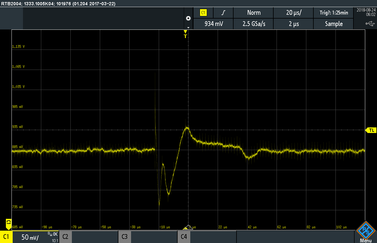
I'm using the ADC in the Tiva part to sample data coming from some analog channels.  The analog channels filter the incoming signals and provide a gain.  The problem arises when I apply the gain (for example 50 up to 100 - it gets progressively worse as I increase the gain).  My input data from the adc in the part shifts when I plug into USB because there seems to be some sort of ground shift.  I only have D+/D-/Gnd signals connecting the Tiva's USB interface to the PC.  The issue has become a very big problem, because the adc monitors the data and triggers when it sees the signal go over a pre-set threshold.  When the device is running and monitoring the inputs everything is smooth, but if I plug in the USB interface while there is any gain applied my signals get shifted up and trigger the device.  This shouldn't happen.  The same shift drops my signal magnitudes when I unplug the USB cable.  

This is a somewhat difficult problem to fit in a forum category so feel free to move this post, but I'm looking for any help I can find to eliminate or at least minimize this as I will have customers using different PCs/Laptops and this will make the product very hard to use reliably.

Thanks!

  • Hello,

    Robbie Valentine said:
    This is a somewhat difficult problem to fit in a forum category so feel free to move this post, but I'm looking for any help I can find to eliminate or at least minimize this as I will have customers using different PCs/Laptops and this will make the product very hard to use reliably.

    We anticipated some unknown unexpected condition as you report may occur between different ground potentials. The goal was to isolate the PC power supply ground from USB port digital ground of the target MCU. One simple step includes adding a low resistance ferrite bead between the two grounds at the USB port, common practice. Alternatively cut the ground trace scrape solder mask install SMT multilayer bead. However it is possible too your PC power supply may have failure or design issues DMM test may reveal, easy enough to replace the power supply. 

    Another point includes the USB miniport shell be isolated from digital ground via parallel capacitor, resistor connected to frame ground or case digital as launch pad. We opted to connect shell  to frame ground trace boarding PCB, indirectly shares AGND via similar RC pair. Where AGND and FGND are thus isolated via parallel 1Mohm, 2200pf DC safety capacitor.  The USB cable shield should not be connected to digital ground as that typically defeats the purpose of the shield! Yet US gets so much "@#$^" imported from over seas where FG was tied to DG as if even being relevant to USB ports or to the connected OTG devices. 

    Perhaps another point of contention AGND if connected to analog ground plane may introduce undesired noise into the ADC from other onboard systems.   

  • Thanks to BP101 for the various suggestions. One thing I will add is to review the TM4C123 system design guidelines at www.ti.com/.../spma059.pdf about the USB routing and the PCB chassis ground design when the board contains external connectors.

    Another question to ask if the ground shift is happening no matter which PCs/Laptops you are connecting to?

  • Hi Charles,

    Would not such issue be greatly amplified when the MCU board is (separately) powered?    (i.e. Not powered via the PC-Connected USB cable?)     And should the PC and MCU board's power supply - be plugged into different AC sources - the voltage 'deltas' CAN prove harmful.

    That said - if the MCU board ONLY receives power via the (single, PC connected USB cable) does this not prove an effective (though operationally limited)  solution?

    To the poster's issue - is it not likely that poster's Board power source is not (shared) by the PC?


    Might the best resolution result from (somehow) equalizing the Ground Voltage - between poster's MCU supply - and the (connected) PC?
    And - achieving that - just may - separate the 'men from boyz...'     Although - off in the distance - is not, 'Consider proper isolation'  -  faintly heard?

  • Hi cb1,

      From the poster's description, the board has a separate power source from the USB power. Can the USB provide sufficient power for the entire board? I don't know what other components are on the board and the overall power consumption. Depending on application there is time that the USB functionality is not needed and if there is only USB power then the board/MCU is dead. But I agree that the solution is to equalizing the ground voltage and ensure there is no noise coupling from one to another when the USB is plugged in. The system design guideline has some recommendation on the PCB chassis ground. That is what I suggested to take a look. 

  • There is always a shift when I plug it into the computer.    I need to verify but I think it changes (bigger or smaller shift) from computer to computer.  It is a battery powered product so i use usb to trickle charge the batter.  I do use usb power when it is plugged in, but it must run off of battery power when disconnected.  

    I apologize, I was wrong when I said I only used usb d+/d- and ground.  I also use usb 5v for power and battery charging when plugged in.

    I will read the design guidelines and get back to you.  One other thing to note is that I'm using a micro d connector and not a standard usb connector.

  • Your writing does not fully/properly/convincingly define the (different) power sources - for your board!      

    Now earlier (first posting) you wrote,  "I only have D+/D-/Gnd signals connecting the Tiva's USB interface to the PC."

    Yet - just moments ago - you,  'Reversed Course' - and now (advise) - that your MCU Board may be  'USB Cable Powered from a PC!'

    Robbie Valentine said:
    I do use usb power when it is plugged in

    Which statement 'Is' really correct?    (such conflict - is (very) troubling!)     And this IS a 'Power Issue' - so it is (expected) that your POWER details will receive full/proper thought, care & presentation!

    Kindly detail your board's (assumed) external power source.    (which as you've (once) noted - is NOT the PC's USB cable.)     Or - is it possible that  your board's 'Battery'  - is the 'main' - yet 'NOT' external - power source?    Such is unclear to me - possibly others - requires clarification.

    You note a 'micro d' connector.    Do you mean the (past) 'D style' connector - as supplied upon the (again past)  RS232 style ports?     Is this a formal, production style cable - or one of (your) manufacture?

    And - as always - does this effect persist across 'ALL' of your MCU Boards?      And across 'ALL' of your PCs.

    It is believed that a 'Battery Powered Laptop' (no connection to the AC mains) - would 'best mate' w/your board - in terms of, 'Ground-Shift Minimization.'       Kindly  test & confirm - this may provide (much) needed insight.

  • cb1_mobile said:
    Although - off in the distance - is not, 'Consider proper isolation'  -  faintly heard?

    As (gently) teased earlier - rather than the 'lesser (questionable) solutions' earlier presented - the addition of a 'PRO, USB Isolator (ADI's  'ADuM3160') will (surely) DO THE JOB!     This device is highly sophisticated - simply 'overwhelms' the (earlier advanced) [pardon] 'bandaids' - and is a proven performer.

    Here's why: ... with standard USB cables the ground connection cannot be avoided.    The only  'Ground-Shifting Solution' is to break that ground loop with a proper USB isolator.      By  galvanically isolating the host from (your) peripheral USB device (MCU) - communication between the two systems will continue and (any) Ground-Loop will be substantially reduced!    (usually eliminated...)

    Although disturbing - It proves (much) to your advantage  to have discovered this 'issue' early - prior to your entering 'production.'      (I'm aware of less expensive techniques to resolve - yet unless your volume is HIGH - you are unlikely to be able to afford our design fees...)

  • Hi Guys,

    Thank you for the responses and I apologize for the "scattered post" as I really should have provided more information.  I have done some testing tonight and I think I have some helpful information to go with some of your points previously.

    Here is a block diagram of my power system:

    I have a single ground plane - everything is connected to the same ground.  I was wrong earlier regarding the USB signals (had my mind wrapped around another product).  5V comes in from the uD connector and goes into a boost regulator.  This boosts the voltage and trickle charges the battery (this is a battery powered product that can run off USB power when plugged in).  The battery is diode protected and the device runs off of USB power when plugged in and the USB power also charges the battery.  One of those two power inputs (battery or USB) then feeds a buck regulator that creates 3.3V for my power plane.  Hopefully this clears things up.  

    Functionality:

    The issue lies in a particular functionality of the product.  You can configure the device to begin reading data (using the Tiva's ADC) and monitoring that data.  It compares the data against a threshold and if the values are higher than the threshold it triggers.  My issue is that when I am in this mode waiting for a violation and plug in the device I get a false trigger.

    Testing:

    I've done some testing and gathered some screenshots tonight.  From what I can see on my oscilloscope when looking at the output of my analog channel when the gain is at 100V/V I get a transient spike when I plug the usb cable into the device.  Said differently, when I am at a high gain I see this transient when I plug the product into my laptop via the USB port.  I see this consistently across my laptop and desktop as well as when my laptop is ONLY on battery power.  

    I'm going to read over your recommendations the rest of the night and check out that AD part.  Thank you for your recommendations and time!  I will do more troubleshooting and gather more test data as well.  I think this type of event normally wouldn't be an issue, but I have such a high gain it is bringing out this small transient.  

  • Thank you for that detailed - yet broadcast response - many questions have been answered.

    That said - as this issue is both 'known' - and 'wide spread' (wide enough that several firms have designed 'dedicated ICs' to (really/properly) resolve)  - questions & comments continue:

    • You earlier noted 'ground shift' - that's not (effectively) in evidence w/in either of the scope caps.    Can you present scope-caps which visually document such 'ground-shift?'
    • Vendor's Charles - and I - both note that the PC's USB cable IS current limited - AND your use of a 'µD' connector - is (almost) certain to  'Add to ground-shift' - due to the small gauge USB cable.
    • You note everything connected to the same (common) ground - yet the 'method' of such connection - is likely to have major impact!    It is believed that a 'Star Ground' - one in which all ground-fed circuit elements tie to a 'common (and beefy) SINGLE point' proves optimal for such application.    You must avoid 'daisy-chaining' the ground traces - in which ground current 'builds' - and exacerbates 'ground-shift!'
    • Ground pcb traces should be as wide and direct as possible - and follow that 'Star' - rather than (reduced) 'point-to-point' pcb trace protocol.
    • You can gain further insight into the (major) cause agents of those 'gain transients' by monitoring the various 'key nodes' of your (assumed) op-amps (instrumentation-amps, better) both 'prior to' and then upon, 'USB Cable Insertion.'

    You must note though - that even following the (above) guidelines - you are unlikely to 'escape' ground-shift.     And - under  especially (unfortunate) conditions - that ground shift has 'Blown-Out' the PC's USB Port!     Such has been documented by several of the major semi-vendors - who recognizing the seriousness of the issue - have invested in the  'Development of dedicated USB isolation ICs!'    These 'isolation techniques' - as reported by semi-vendors - and confirmed (repeatedly) by firms such as mine - prove the ONLY means to effectively resolve, 'Ground Shift' - and make the, 'Attachment of the USB cable, 'SAFE!'     And do note - you have 'ZERO Control' over the quality of USB Port (especially its Ground Voltage) - which clients' employ to 'feed your board!'

    In summary - I'd seriously consider two 'areas of attack'  - to (really & effectively) resolve your, 'Power and Ground-Shift' issues:

    • Deploy the dedicated USB Isolator IC - as earlier recommended   (i.e. the 'Ground-Shift' Slayer!)     (Attn: major semi-vendors - (c) 2018 'cb1' - all rights reserved)
    • Deploy an 'adequate' power supply for your board - escape reliance upon the (many unknown - surely (some) questionable) PC, USB Ports.     Wall-warts have dropped in price - and will 'REMOVE the Variability' - which the (always unknown) PCs' (plural) USB Ports provide.

    Indeed - if your boards presently exist in some volume - you are likely to 'resist.'     You then have 'traded' security and 'the known' - for (hoped for) 'getting by' & (maybe) cost-saving.    

    Yet your (getting by) 'COSTS' will remain - both:

    • to your reputation
    • and necessitated by (predictable & on-going) 'field failures'  

    and this argues (overwhelmingly) in favor of the 'REAL Solution.'     (i.e. properly isolated and powered!)     Big SEMI would  NEVER 'have made such 'investment'' - if this 'Ground-Shift' issue was NOT 'Wide-Spread & SERIOUS!'

  • Robbie Valentine said:
    My issue is that when I am in this mode waiting for a violation and plug in the device I get a false trigger. Testing:

    Both captures as CB1 notes is not indicating ground shift, rather an inrush current surge. Perhaps a result of computer +VBUS powering boost regulator, seemingly power on overshoot! If boost regulator has EN pin slowing down the period (soft start) via RC should remove overshoot. We do the same with +5 buck down to stop nasty inrush to 3v3 LDO.

    Might you include where in your block diagram the ADC monitors for transient and why/what is the monitor for/doing?

  • Hello BP,

    What you write (almost) matches my sense - it is (more) expected that the USB Cable is tasked w/CHARGING one or several Filter Caps - and as they (likely) 'Start from (near) zero voltage' - therein lies the VAST Bulk of the current surge.     Those FILTER CAPS - NOT so much the 'boost regulator' - are almost certainly the MAJOR CONTRIBUTOR to current surge.

    That said - as earlier directed - use of an external supply - solves such  current  surge issues - completely!

    And - any/all of  your/others effort to reduce 'inrush' - will have ZERO EFFECT upon poster's 'Ground-Shift' - which proves the 'raison d'être' here - does it not?

  • It has not been proven such ground shift being culprit of transient response (capture) from suspected current monitor? Recently too dealing with similar issue INA240 and note the first spike downward being (sustained) via VBUS slower charge current, often limited 250ma USB ports. Do you not agree soft start should be part of any boot regulator to reduce effect of large output capacitor charging di/dt, overshoot dv/dt recovery?

    Point being external DC supply period of under/overshoot being much harder to detect/capture. Most all current monitors transient response constrained by datasheet specific parameters derived from differential amplifier gain. In this case less OP gain reduces the transient peak output, added input filtering reduces/removes the slower charge periods tripping fault.

  • It is believed that you are 'Shifting Poster's Thread' to your (ongoing & special) interest.    Poster's MAIN interest - as (clearly) and (properly) denoted w/in his Subject Line - is 'Ground Shift.'

    Again - with a proper, external supply, and NO CONNECTION between the USB's 5V and poster's board - AND the specified 'USB Isolator' - any such  Ground Shift OR 'high-gain transients' should be quelled.

    The above was 'DELIBERATELY CRAFTED' to,  'COMPLETELY RESOLVE'  ...  ALL Poster concerns!    (First Ground-Shift - and then 'gain-induced' transients.)

    Rather than,  'Steer this thread to YOUR (special) interest'  -  a separate/dedicated thread - clearly labeled with your ongoing desire - would escape the label of  'hijacked!

  • Also notice the buck regulator (block diagram) has line leading to Tiva but is that being monitored hot input to analog cannel? How has poster increased/reduced analog gain if not by current monitors specific OP gains placed between the two. It otherwise would be RC filter hot off buck regulator which is prone to any downstream di/dt, dv/dt sent out of boost regulator.

    Other words difficult to detect any USB current fault from monitoring analog hot off buck regulator even with added RC. TI makes nice USB switch TPS2051 for VBUS power distribution with built in OC detection pin.

  • cb1_mobile said:
    The above was 'DELIBERATELY CRAFTED' to,  'COMPLETELY RESOLVE'  ...  ALL Poster concerns!    (First Ground-Shift - and then 'gain-induced' transients.)

    Capture analog signal of AINx ? most notable no evidence of said ground shift being exhibited in posted signal. Analog signal clearly shows the effect of VBUS inrush current and slower recovery period resulting from boost regulator cap charge being (delayed). Seemingly result of much lower supply current of computer limited VBUS especially if an external DC supply removes the boot regulator condition from the discussion. 

    The boost regulator has yet to be ruled out being in question, note the two series diodes reverse recovery periods show in posted capture. Two recovery periods are not an artifact of ground shift, rather indicate the diode drops reacting to VBUS current flow.

  • May we (simply) 'PAY YOU NOW' - thus enable (poster's) 'Truck' to continue on its way - minus (unwanted) driver stress during 'truck's take-over?'

  • cb1_mobile said:
    What you write (almost) matches my sense - it is (more) expected that the USB Cable is tasked w/CHARGING one or several Filter Caps - and as they (likely) 'Start from (near) zero voltage' - therein lies the VAST Bulk of the current surge.     Those FILTER CAPS - NOT so much the 'boost regulator' - are almost certainly the MAJOR CONTRIBUTOR to current surge.

    Mon ami where do you think Filter Caps are located, output boost & buck regulators? Seemingly backlash from 2 steering diodes show very slow recovery perhaps more a focal point. Might a second capture same analog point with external DC supply give clue as to why 2 diodes seem to buck wildly from slower current change with a battery potential in the mix? 

    Schottky diodes have various FV drops and RV recovery speeds to choose from, updated capture may reveal an easier WA. Doing PCB redesign adding USB isolation even a TPS switch = time lost, less GOV contracts tax prayer dollars flipping the bill. Poster can actually get or measure the recovery time of the diodes from zoomed captures.

  • You've convinced me!    ALL of the semi-giants should assemble (your basement) - 'Admit their Folly' & abandon their dedicated, 'USB Isolators!'

    And - I suppose - the employ of a (proper) external supply (along w/'preventing' the USB cable's '+5V' entry) 'CONTINUES'  to escape your note!

  • cb1_mobile said:
    And - I suppose - the employ of a (proper) external supply (along w/'preventing' the USB cable's '+5V' entry) 'CONTINUES'  to escape your note

    Again a second scope capture would prove or disprove the speed of troublesome capacitor charge relative to battery reverse charge being more in question than any ground shift occurring. Yet seemingly escaping any analysis battery charge presence of not 1 but 2 diode drops and boost regulator VBUS powered, versus (testing) issue with external supply on same VBUS pin. USB power source is the posters design principle not simply adding an external power source to remedy the current surge.

    Charles brings that point how much current does the VBUS pin source from computer ? very important fact not being disclosed. Micro or mini USB cable must provided the same 250ma current through computer attached peripheral VBUS pins. The newer USBv3 provides 500ma on VBUS pin, if not mistaken.

    Glad you now agree both scope captures do not present evidence of ground bounce (shift) rather perhaps the boost regulator bouncing down toward ground. Fast Schottky diodes + soft start regulators required for circuit (posted) to slow any perceived current surging VBUS pin upon plugging. Note too (poster) fuse must be inline battery and or VBUS pin to protect customer computer.

    cb1_mobile said:
    You've convinced me!    ALL of the semi-giants should assemble (your basement) - 'Admit their Folly' & abandon their dedicated, 'USB Isolators!'

    Far to early to know GND shift occurs absent (captures) triggered to power source relative to AINx pin bouncing. Speculation is the next best clue often called others reaching, poster reaches yet no rep-remand, leaves moi speechless!

  • Guys,

    Thanks again for all the feedback.  I didn't follow the entire conversation, but I think I understood most of it.  I have take some more screen captures and tried to improve on the block diagram of how the system works.  

    The signals in the scope captures are as follows:

    yellow - zoomed in view of the 5V input from USB.

    green - analog Vcc which is shown in the BD as 3.3V output from the analog LDO.  This powers the op amps in the filter.

    orange - 3.5V digital Vcc.  This powers the Tiva part.

    ------------------------------------------------------------------------------------------

    You can definitely see some high frequency transient there which as was mentioned could be due to inrush current.  The boost converter I'm using also doesn't have a soft start feature (FYI) it is the LMR62014.  I'm wondering if switching this part out to a soft start capable boost converter would solve this problem?  

    I really like the USB isolator.  Thank you for that recommendation I will keep it in mind for future designs.  Unfortunately as you could probably expect I can't have an external power supply even though that would be more ideal than USB power.  

    One thing to note in the schematic screenshot (I understand it may be hard to see clearly) there is a fair amount of capacitance on the buck converter input.  You can see I have a good bit of capacitance and this is something I could most likely bring down.  I had initially designed it in due to a step load issue.  I seem to be wrong thinking this was a grounding problem.  It looks now to be boost converter/in-rush current related.  Thank you again and I hope this information sheds more light on what I'm doing.

    The probes are grounded to the board by clipping them on to a short wire.  I"m using the ~4" ground alligator clips for each of the 3 probes.

  • Thank you - crack helper crüe had not heard from you for awhile - good to note that you are persisting.

    If  your  'untethered' (to the PC) board is (only) powered from the battery  - and the 'voltage-drop' between your 'PC's USB Ground and  the op-amp's Ground' is nominal - then the 'USB Isolator' may 'not' be required.    However - caution is (still) required - as you cannot count upon all users employing 'proper, short length, USB cables' and the condition of client's USB Port will always be 'unknown.'    Should a long (> meter) USB cable be employed - unless of 'high' quality - the added inductance of that cable is (sure) to add complications.    Again - to remove this 'variability of 'PC, USB Port performance' - an external (wall-wart) supply remains recommended.

    Follows (some) commentary:

    • schematic does not  illustrate that  'Ground'  is connected between your board & PC.    (we're shown (only) the right-hand side of the board's USB connector)
    • the boost converter - when 'untethered' - sees its 'V_in' pin 'float.'     I doubt that's a 'good idea' - better to apply a resistive path to Ground.    (perhaps 10K - yet RTFM)
    • your scope caps 'trigger' mid-screen - more of the 'areas of interest' would reveal if you triggered from (near) the left edge (say 10% position)
    • it was past suggested that you 'scope-monitor' the critical 'op-amp nodes' - especially during your board's 'moment of tethering!'    (it is likely that you can 'better filter' - at/around the op-amp - than 'elsewhere.'
    • 'beefed-up' Ground traces - rendered via 'Star Connection' (NEVER daisy-chain) ARE required
    • can you (really) rely upon the delivery of adequate current (w/out voltage sags) from (each) user's USB Port?   Your MCU draws over 200mA alone - does it not?
    • and - asked earlier - yet never answered - Why is this 'transient alarming' an (issue?)    It (transient arrival) IS known - and 'disappears' quickly!     Your MCU can (surely) detect the cable's insertion - and 'PREVENT ANY ACTIVE ADC CONVERSIONS' - until 'circuit quiet' has again restored!

  • I remain 'unconvinced' of the 'efficacy'  to (only) employ the PC's USB Port for 'Normal, Tethered Board Operation' and/or 'Board's Battery Charging.'    

    'MANY' of my firm's clients have been 'burned' by, 'Falling to the 'ease' of USB Port Power!'     Power always was - and remains - JOB ONE!    And - should power prove inadequate - even the best design will be compromised - sometimes (even) fatally!    My firm notes that this vendor has produced a 'most excellent' Tech Paper,  'Powering Electronics from the USB Port.'    Such appears a (near) ideal source - to determine if  'my reservation'  re: USB Power - has merit.   

    A key, 'USB Power Requirements' table (USB 2.0 spec) - appears w/in the report:   (true copy follows)

    Another here (guessed/reached) at USB 2.0 as providing 250mA - and USB 3.0 as providing 500mA - both wrong.    (USB 3.0 may provide up to 900mA)

    In poster's usage - that 100mA limitation - must receive focus!     Here now - key detail (again a 'true copy') directly from this vendor's Tech Paper:

    "Another unique requirement of the USB power interface is the different current draws allowed.    When a device is first connected to the USB, its bypass capacitor could be charged abruptly and create a glitch on the host equipment supply.    The USB specification resolves this problem by limiting the initial power surge in two ways.   The peripheral device is allowed only a small (<10-µF) bypass capacitor, and the charge drawn from the bus is limited to 50 µC over a specified time.    Larger capacitors can be used if inrush limiting is provided.

    Once the USB is connected, there are further limits on current draw.  The host first recognizes the peripheral as low-power, allowing it to draw less than 100 mA of current.  The peripheral can ask the host to recognize it as a high-power device in a process called “enumeration.”    Once enumeration is completed and permission is granted, the allowed peripheral current is increased to 500 mA."

    I've left that extract 'pure/unaltered' - yet key points within demand our attention:

    • When a device is first connected to the USB, its bypass capacitor could be charged abruptly and create a glitch on the host equipment supply.    Just as you've (and others) have noted!
    • The peripheral device is allowed only a small (<10-µF) bypass capacitor.    And you appear (via my intense 'squint') to have complied - yet such small cap filters little!
    • Host first recognizes the peripheral as low-power, allowing it to draw less than 100 mA!    This IS insidious - 100 mA may not enable the MCU to 'fully/properly' perform!
    • Peripheral (your MCU) can ask the host to recognize it as a high-power device.   (called 'enumeration')    
    • Once enumeration is completed and permission is granted, the allowed peripheral current is increased to 500 mA."    Yet - can your MCU board achieve this 'enumeration' - while (throttled) to 100 mA?    And that 100 mA current applies to your ENTIRE Board - NOT (just) to the MCU!

    Note that 'NONE of these 'rules/regulations' spring from my firm/myself.    And they surely DO - land 'HARD' upon 'YOU' and (others) - who  seek to 'Trade Comfort/Ease' for 'Proper & Robust'  External Power!

    And - should it 'not' be noted - that your 'Transient Glitch Issue' - disappears when a (proper) External Supply - Powers your board!     (even though - and especially though - the 'ease' of the USB Port has been replaced by 'LESS GOVERNED/RESTRICTED' POWER MANAGEMENT protocol...)

    For those seeking Real 'USB Powered' Detail' - vendor's Tech Paper is linked, below.    Such 'investigatory effort' always trumps 'Reach and/or Guess' - (regularly) practiced here.

    http://www.ti.com/lit/an/slyt118/slyt118.pdf

  • cb1_mobile said:
    Another here (guessed/reached) at USB 2.0 as providing 250mA - and USB 3.0 as providing 500mA - both wrong.    (USB 3.0 may provide up to 900mA)

    The USB specific guide lines you posted for USBv2 and VBUS current does not suggest PC mother board designers followed it or even provisioned it for 500ma, thus 250ma being more prudent. I have fixed several USBv2 mother boards restricting VBUS current via 20 ohm series resistor to 250ma. And not via USB controllers energy use being an ACPI compliant peripheral under windows low power battery modes. Perhaps VBUS current consumption more aimed at Lap tops? The PC maximum high power 500ma perhaps also combination of VBUS capacitor charge being able to deliver short burst for inrush charge of connecting USB target?  

    cb1_mobile said:
    Once enumeration is completed and permission is granted, the allowed peripheral current is increased to 500 mA."    Yet - can your MCU board achieve this 'enumeration' - while (throttled) to 100 mA?    And that 100 mA current applies to your ENTIRE Board - NOT (just) to the MCU!

    Seriously question when the 100ma is being throttled by Windows ACPI compliant energy control if not specifically configured in the BIOS to do so. That would also infer the mother board has such throttle provision and finding such provision in older USBv2 perhaps even higher reach.

  • Just for kickers what happens when the battery is left out when you plug in the USB cable?

    Can you probe the Boost output and present it both here and on WEBENCH power forum. Gurus there may have WA solution beyond our simple observations pointing out what you now suspect. Highly suggest testing with fully drained battery, may require MCU reset hold off even with soft start in the mix.
  • BP101 said:
    Seriously question when the 100ma is being throttled  ...  finding such provision in older USBv2 perhaps even higher  reach.

    There is 'NO REACH' - I have  (instead) provided (very) relevant, 'direct source material from experts'  - engaged by (this) 'world-class semi-vendor.'  Such (deliberately) counters any 'fair charge' of  'reach.'

    Little of my report is (uniquely) my view/opinion - and that holds (especially) true - in regard to the 100 mA current limit - (initially) enforced under USB v2.0.    (prior to 'successful' enumeration)    (Is it possible that your assertion of 'reach' - is in fact  once more ... (your) reach?)

    The tendency of (some) here - to (so often) provide their unjustified, '(so) limitedpersonal findings & singular beliefs'  - cannot  'compare nor compete'  w/ 'properly sourced - expert, highly relevant, source material!'

  • It would be a far reach to (believe) verbatim the updated USBv2 specification being not many computer boards if any hold to such controls being default enabled. Again typical default BIOS configurations do not have ACPI compliant USB port energy controls enabled nor does Widows 7, who knows about W10.

    Though USBv2 specification may have been later revised for W7 or simply did not exist in 2002, limiting 100ma. Yet that still would be a reach to assume VBUS 100ma limit being default BIOS configuration and 500ma with 20 ohm resistors in series VBUS pin makes it reach. The updated USBv2 specification has not elaborated how or when 100ma limit occurs, if ever. I don't recall there being USBv1 or didn't care since Compaq servers laptops did not deploy USB ports in 1999-2002. It would seem USBv2 specification was open to each manufactures discretion and revised as operating systems gained more treads into BIOS controls. All our MSi mother boards (AMD/Intel) never document BIOS enabled ACPI controls of the USBv2 VBUS pin current let alone it being limited to 100ma at any time.

  • Once more - in high accord w/'the usual' - one here has presented, 'Relevant, Expert, Source Material.'      

    And 'another' has presented 'undocumented, highly 'personal belief' - without (any) benefit of   'justification or external documentation.'

    BP101 said:
    not many computer boards if any hold to such controls being default enabled.

    Is this not - quite clearly - ONLY your 'opinion'?    How compelling is that?      Even when - and especially when - this vendor's two experts reported:  (a true copy - very first page of their report follows:)

    "Once the USB is connected, there are further limits on current draw.    The host first recognizes the peripheral as low-power, allowing it to draw less than 100 mA of current.    The peripheral can ask the host to recognize it as a high-power device in a process called “enumeration.”    Once enumeration is completed and permission is granted, the allowed peripheral current is increased to 500 mA.

    The USB 1.0 specification has been active since its release in November 1995.    Products that were delivered to the 1.0 specification had no official logo associated with them.     Many times the products did not fully meet the current-limit requirements, which usually was not a problem with the product connected to a PC.    However, problems did arise when there were multiple products connected in a hub arrangement.      With the release of the 2.0 specification, certified products will be marked with a logo.   The certification promises to be more rigorous, and designers should expect to  meet the requirements of the new specification.  (2.0)"      

    You appear 'not' to have read/reviewed the document (earlier) presented - which stands in 'high challenge' to (your) 'personal' opinion... (Has not 'your view' - died w/the arrival of USB 2.0?)

    (There IS (some) chance that your 'opinion' proves (on occasion) correct.     Yet - your 'Search & Gather of Appropriate, Expert, Source Material'  (in support of your 'hunch')  somehow - has (again) 'Escaped your submission!'     And simple, highly 'personal opinion' proves of  (little) value or interest...

  • cb1_mobile said:

    You appear 'not' to have read/reviewed the document (earlier) presented - which stands in 'high challenge' to (your) 'personal' opinion... (Has not 'your view' - died w/the arrival of USB 2.0?)

    (There IS (some) chance that your 'opinion' proves (on occasion) correct.     Yet - your 'Search & Gather of Appropriate,


    Today checked earlier Pentium 4 Asus (Phoenix AWARD BIOS), USB ports support bot V1 & V2 with ability to enable S3 support. Repairs made mother boards prior to 1996 (USBv1) more minimum 20 ohm series with VBUS pin. That was not a personal opinion mostly based on experience.Today looked at few older mothers in the expent pile only then to recall fuzzy memory past repairs being USBv1 prior to release of USBv2.  

    cb1_mobile said:
    "Once the USB is connected, there are further limits on current draw.    The host first recognizes the peripheral as low-power, allowing it to draw less than 100 mA of current.    The peripheral can ask the host to recognize it as a high-power device in a process called “enumeration.”  Once enumeration is completed and permission is granted, the allowed peripheral current is increased to 500 mA.

    If only the OTG host port EK-TM4C1294XL was capable same 100ma current limit to device. OTG does have over current fault signal (PQ4) and switching PD6 for OTG Target_VBUS3.2C though (JP1/3-4). Oddly +VBUS via Target_VBUS3.2C was still present via U4 with JP1/3-4 strap removed, PD6 being Hi or Lo.  The USB client enumeration via TI bulk device CDC driver was not written to support ACPI energy controls for USBv2.0 peripherals. That case VBUS pin should supply 500ma all times, 10 ohms series resistor may have replaced 20 ohm of USBv1. Sadly had not 1 but 2 MCU's VBUS pins (PB1) shorted out from over current spike during plugging OTG port and host device enumeration Via CDC driver. So I seriously doubt any such ability in vendors HID drivers may even exist and 100 ohm series resistor was added to restrict mayhem.   

    Perhaps vendor was speaking of HID drivers having some control over VBUS pins during enumeration, being ACPI is an OS compliance feature for BIOS integration not the CDC driver specifically. Current control of VBUS pin would specifically fall under BIOS control of the USB peripheral hardware embedded device controller if and only if it was designed to limit VBUS current to100ma. Perhaps USBv2 S3 support being enabled provides similar ability ?, Asus & MSI manuals have little to no details under USB configuration or MB specifications pages.  

  • Your data (remains) anecdotal & personal - thus far too limited to prove compelling.     Note that vendor's experts did state that USB v2.0 'had teeth' and that the USB logo was granted (only) to those devices which complied w/the 2.0 USB spec.    (no anecdote - nor personal - there!)

    Several times now you've mentioned a 20Ω series R (enforced upon the PC's +5V output.)      And now - you've 'goosed' that value - UP to 100 ohms!

    BP101 said:
    and 100 ohm series resistor was added to restrict mayhem.  

    Yet - SO CLEARLY - your claim of  100Ω addition to, 'RESTRICT MAYHEM' - must be REPLACED WITH - 'CAUSED MAYHEM! '

    Neither of your reported resistor VALUES (earlier 20 & today 100Ω) proves possible!    (Again - that's the DANGER of  'personal opinion' - MINUS (any) 'Facts in Support!'    

    You DO realize that w/an (initial) 100mA current flow & series R of 20Ω - the PC Port's +5V USB Output would DROP by (20*.1) or 2V - yielding ONLY '3V'  for the USB device!     And your latest (pardon) extreme 'reach' - (100Ω) - would DROP the PC Port's +5V USB Output by (100*.1).           You can do that math!    

    (RAW personal Opinion has BADLY FAILED YOU (again) - has it not?)      

    Your 'wish' is clearly to 'prove helpful' - yet the 'On-going (vulnerability) to serious mistake' - imposed (always) by reliance upon strictly (personal experience/opinion) - proves an 'Unfortunate - yet all too likely consequence...

  • Hi Robbie,
    Both cb1 and BP101 provides various good insights and suggestions. Do you still need assistance in this thread or you can close this thread?
  • Hello Charles,

    In the defense of (others) arriving here - might we remove the following from (any) 'Representation of a 'GOOD Suggestion?'

    BP101 said:
    So I seriously doubt any such ability in vendors HID drivers may even exist and 100 ohm series resistor was added to restrict mayhem.   

    Adding such 100Ω resistor - in series w/the PC's +5V 'feed' via the USB Port - even if  (only) 25mA current flows - would reduce the PC's USB Port provided +5V to (just) 2.5V!     That proves (VERY FAR) from Good - don't you agree?

    Do we not 'OWE' forum readers - (some) caution - when such 'clearly failed'  reports and/or methods - are 'presented?' 

  • Hi cb1,
    I had to sort of go back to the earlier replies to understand the contexts of the 100ohm. I think users can make their judgement about it. I will only say that the TI EVM/LP only takes the USB's 5V supply through the current-limiting switch and then the LDO to supply the MCU. There is no series resistor placed on the power supply path.
  • The 'over-reach' of 'PC' explains so much...

    If the addition of a 100Ω resistor - in series w/the PC's sourced +5V - to be supplied to a 'mated USB device via the USB cable' qualifies (in any way) as a 'good solution' - then our 'Understanding & Use' of language - has 'Left the Building!'

  • Hi Charles CB1,

    I checked my 2004 Soyo PV4+ mother board (in box) no 100 ohm to USB controllers 4 ports VBUS pins located on the back plate. However to my surprise the front two additional ports wired to the ATX metal case USB ports, the VBUS pins are hot wired direct to the DC power supply +5V with absolutely no current limiting other than crow bar of 30 amp +5v supply.

    I would have to agree with CB1 on some of his assessments, newer mother boards make an attempt at some kind of VBUS current regulation on the hardware level. I say hardware since the USB peripheral may be plugged prior to OS enumerating the plug and play peripheral. That may be where we parted on the understanding of VBUS pin current being limited to 100ma during enumeration. So the updated V2 standard provides no VBUS current at all or seemingly multi peripheral device chip (self) limits current to 100ma until it has been fully enumerated via ACPI BIOS control of the OS & device driver being loaded.

    Point being to imply during enumeration current limiting is not the same as saying prior to enumeration as it relates to ACPI controls.
  • No over reach when both front USB ports had no current limiting USBv2 updated standard. Please watch snide remarks referencing others for simply adding to the conversation in a good way, that may not be your way!
  • Has (necessary) CAUTION - somehow - been demoted to 'snide?'     The suggestion by (one) here - to insert a 100Ω resistor - in series w/the PC's, USB Port's +5V - is patently unwise.     And the claim that such 'added resistor' ... "Restricts Mayhem"  is blatantly  WRONG!   

    Might you identify, "How much current can be delivered via (any) USB cable - burdened with such 100Ω resistor - in series w/the +5V cable lead - routed to the USB device?"

    Is the 'indefensible' (again) to be defended?      We (really) do not want  (other forum users) - to add that  (clearly mistaken 100Ω series resistor) in-line w/the USB Cable's +5V feed  - don't you agree?

    The 'intent' - far from 'snide' - was to encourage you to (better proof-read) - and to edit away - that (unwise & harmful) 100Ω resistor's addition...

    You should note - as well - that your, 'Promotion of such 100Ω 'series resistor' occurred on Sept 29.'      The 'Incorrectness' of that value was noted - and posted here  - that same day.    (Enabling plenty of time for you to, 'Cover your tracks' - and DELETE that failed (100Ω series R - suggestion!)   

    There proves a (vastly) superior means to, 'Accept and Admit - one's mistake.'    Post logged below (in which I solved a user's, 'Slave SPI issue') illustrates a, 'Proper Admission of Mistake' without (at all) attacking the (identifier) - of such mistake!    

    Cb1 quote (Fri, Sept 07 - 19:16)  "And indeed - just as you (very) well noted - (and I (completely) missed) the 'blocking enforced by SSIDataGet() will (indeed) - insure that a 'SPI time-out' occurs."

    https://e2e.ti.com/support/microcontrollers/tiva_arm/f/908/t/726168