This thread has been locked.

If you have a related question, please click the "Ask a related question" button in the top right corner. The newly created question will be automatically linked to this question.

EK-TM4C1294XL: is it possible to shoot three single shots at the same time?

Part Number: EK-TM4C1294XL
Other Parts Discussed in Thread: STRIKE

Hello,

i want to create three single shots as a gate signal for three mosfets. the duty cycle is variable and can be changed with a touch display.

i configured three timer in single shot mode and tested it.

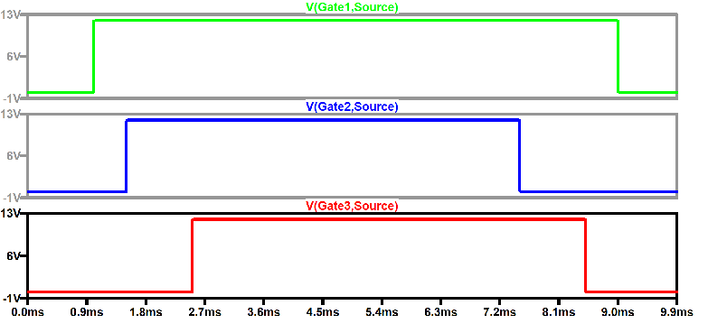
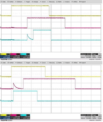
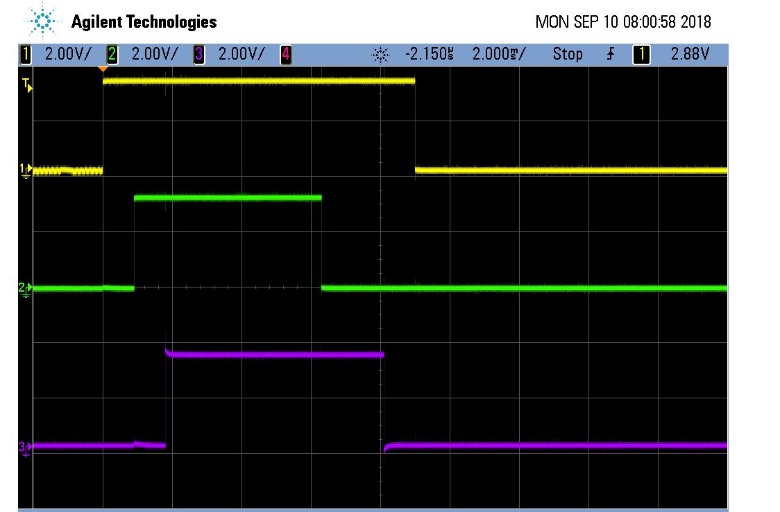
but the one shots comes one after another and not at the same time (similar to the picture)

is it even possible to do three one shots at the same time? What i am doing wrong?

thank you for your help.
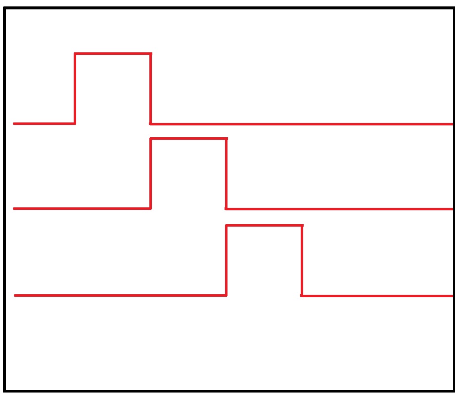
my code here:

/*
* Timer Config
*/
void timer_gpio_config(void){ //void timer_gpio_config(uint8_t *Slider_E_1){
/* Enable Timer */
SysCtlPeripheralEnable(SYSCTL_PERIPH_TIMER0);
SysCtlPeripheralEnable(SYSCTL_PERIPH_TIMER3);
SysCtlPeripheralEnable(SYSCTL_PERIPH_TIMER2);
SysCtlPeripheralEnable(SYSCTL_PERIPH_GPIOF);
SysCtlPeripheralEnable(SYSCTL_PERIPH_GPIOG);
SysCtlPeripheralEnable(SYSCTL_PERIPH_GPIOL);


/* Configure Timer A in single shot mode */
TimerConfigure(TIMER0_BASE, TIMER_CFG_A_ONE_SHOT); //TIMER_CFG_A_PERIODIC TIMER_CFG_A_ONE_SHOT
TimerConfigure(TIMER3_BASE, TIMER_CFG_A_ONE_SHOT);
TimerConfigure(TIMER2_BASE, TIMER_CFG_A_ONE_SHOT);

GPIOPinTypeGPIOOutput(GPIO_PORTF_BASE, GPIO_PIN_3);
GPIOPinTypeGPIOOutput(GPIO_PORTG_BASE, GPIO_PIN_0);
GPIOPinTypeGPIOOutput(GPIO_PORTL_BASE, GPIO_PIN_4);

GPIODirModeSet(GPIO_PORTF_BASE, GPIO_PIN_3, GPIO_DIR_MODE_OUT);
GPIODirModeSet(GPIO_PORTG_BASE, GPIO_PIN_0, GPIO_DIR_MODE_OUT);
GPIODirModeSet(GPIO_PORTL_BASE, GPIO_PIN_4, GPIO_DIR_MODE_OUT);

/* Registers a function to be called when an interrupt occurs P:355 */
IntRegister(INT_TIMER0A, timerIntHandler);
GPIOIntRegister(GPIO_PORTF_BASE, gpioIntHandler);

IntRegister(INT_TIMER3A, timerIntHandlerTimer1);
GPIOIntRegister(GPIO_PORTG_BASE, gpioIntHandler1);

IntRegister(INT_TIMER2A, timerIntHandlerTimer2);
GPIOIntRegister(GPIO_PORTL_BASE, gpioIntHandler2);

/* The specified interrupt is enabled */
IntEnable(INT_TIMER0A);
IntEnable(INT_TIMER3A);
IntEnable(INT_TIMER2A);

/* Enables the processor Interrupt */
IntMasterEnable();

/* Sets the Interrupt type for the specified pin */
GPIOIntTypeSet(GPIO_PORTF_BASE, GPIO_PIN_3, GPIO_HIGH_LEVEL);
GPIOIntTypeSet(GPIO_PORTG_BASE, GPIO_PIN_0, GPIO_HIGH_LEVEL);
GPIOIntTypeSet(GPIO_PORTL_BASE, GPIO_PIN_4, GPIO_HIGH_LEVEL);

/* Enables the specified GPIO interrupts */
GPIOIntEnable(GPIO_PORTF_BASE, GPIO_INT_PIN_3);
GPIOIntEnable(GPIO_PORTG_BASE, GPIO_INT_PIN_0);
GPIOIntEnable(GPIO_PORTL_BASE, GPIO_INT_PIN_4);

/* Enables timer interrupt sources P: 543*/
TimerIntEnable(TIMER0_BASE, TIMER_TIMA_TIMEOUT);
TimerIntEnable(TIMER3_BASE, TIMER_TIMA_TIMEOUT);
TimerIntEnable(TIMER2_BASE, TIMER_TIMA_TIMEOUT);
}

void timer_start (){

TimerLoadSet(TIMER0_BASE, TIMER_A, 12000001 * Slider_E_1);
GPIOPinWrite(GPIO_PORTF_BASE, GPIO_PIN_3, GPIO_PIN_3);
TimerLoadSet(TIMER3_BASE, TIMER_A, 12000001 * Slider_E_2);
GPIOPinWrite(GPIO_PORTG_BASE, GPIO_PIN_0, GPIO_PIN_0);

TimerLoadSet(TIMER2_BASE, TIMER_A, 12000001 * Slider_E_3);
GPIOPinWrite(GPIO_PORTL_BASE, GPIO_PIN_4, GPIO_PIN_4);
}

void turbo_boost(void){
GPIOIntDisable(GPIO_PORTL_BASE, GPIO_INT_PIN_3);
GPIOIntDisable(GPIO_PORTL_BASE, GPIO_INT_PIN_4);
GPIOIntDisable(GPIO_PORTL_BASE, GPIO_INT_PIN_5);

GPIOPinWrite(GPIO_PORTL_BASE, GPIO_PIN_3, GPIO_PIN_3);
GPIOPinWrite(GPIO_PORTL_BASE, GPIO_PIN_4, GPIO_PIN_4);
GPIOPinWrite(GPIO_PORTL_BASE, GPIO_PIN_5, GPIO_PIN_5);

TimerLoadSet(TIMER1_BASE, TIMER_A, 120001 * Slider_E_1);
}

void gpioIntHandler(void){
/* Enables the timer */
GPIOIntClear(GPIO_PORTF_BASE, GPIO_HIGH_LEVEL);
TimerEnable(TIMER0_BASE, TIMER_A);
}

void gpioIntHandler1(void){
/* Enables the timer */
GPIOIntClear(GPIO_PORTG_BASE, GPIO_HIGH_LEVEL);
TimerEnable(TIMER3_BASE, TIMER_A);
}

void gpioIntHandler2(void){
/* Enables the timer */
GPIOIntClear(GPIO_PORTL_BASE, GPIO_HIGH_LEVEL);
TimerEnable(TIMER2_BASE, TIMER_A);
}

void timerIntHandler (void){
GPIOPinWrite(GPIO_PORTF_BASE, GPIO_PIN_3, 0);

/* Clears timer interrupt sources */
TimerIntClear(TIMER0_BASE, TIMER_TIMA_TIMEOUT); /* Breakpoint hier setzen abi */
}

void timerIntHandlerTimer1 (void){
TimerIntClear(TIMER3_BASE, TIMER_TIMA_TIMEOUT);

GPIOPinWrite(GPIO_PORTG_BASE, GPIO_PIN_0, 0);
}

void timerIntHandlerTimer2 (void){
TimerIntClear(TIMER2_BASE, TIMER_TIMA_TIMEOUT);

GPIOPinWrite(GPIO_PORTL_BASE, GPIO_PIN_4, 0);
}

  • It is assumed that your, 'Shoot Three Single Shots'  was a joke or ... 'Play on Words' ... or just 'Spur of the moment Wording.'      Might you enlighten?

    I've not time - at the moment - to provide a 'full/proper' answer.     (later - early evening (US - CST) I may be able to amplify...)

    Here - some of my key findings:

    • You employ 'GPIOPinWrite()' - yet that's a 'time and code adding'  indirection!      And impairs - rather than aids - your objective...
    • Instead - each Timer has '2' dedicated I/O pins - and when configured in One Shot Mode (Output)  - there is NO NEED for you to implement GPIO - nor GPIOPinWrite()!    Each Timer  Outputs (far more efficiently & automatically) FOR YOU!     (that same Timer pin switches to 'Input Mode' during Edge Count & Edge Time operation - and becomes 'output' during PWM and One-Shot!)
    • To generate all 3 such Timer Signals - in sync - I suspect depends upon:
    • the capability of the calling TWare function - to enable 'all 3 Timers' simultaneously - AND then each Timer's response proving equal
    • should NO TWare function exist to achieve such 'multiple, simultaneous Timer 'trigger function' - you may have to resort to 'DRM' coding
    • for 'DRM' or (even) 'ASM'  to succeed - it is required that the  'Capability to 'Synchronously' Enable Multiple Timers'  must (reside) w/in a  SINGLE Timer Register.   (which allows your simultaneous toggle of 'all 3' Timer 'Control/Enable bits' - via a  SINGLE Function Call!

    It must be noted that your 'bit large' timing diagram revealed the 'dependency' of each (following) Timer Output to 'Await the completion' of its predecessor - which (of course) was/is NOT your objective.

    The clues provided should best enable (your) resolution of this issue.    Again - the structure of the MCU's Timer Register (which may - or may not) provide for 'multiple, simultaneous Timer enabling' is (REALLY) the 'BIG DEAL' (actually the WHOLE DEAL) here!

    As a (far less effective) work-around (almost) - you CAN write to 3 GPIO w/a single function call - and all 3 will respond 'IN SYNC!'      Although then ' you' will (enjoy) the management of all timing - MANUALLY.    (Welcome to 1985 - and the Intel 8051 - and/or many derivatives...)

    [edit]:  15:50 CST - After writing I recalled the following:

    • You can (easily) achieve,  'TWO Split Timers - commanded to One-Shot - and Sync'ed' provided they are, 'Resident w/in the same Timer Module!'   (how basic, that)    Here's how: 

    TimerConfigure(TIMERN_BASE, (TIMER_CFG_SPLIT_PAIR | TIMER_CFG_A_ONE_SHOT | TIMER_CFG_B_ONE_SHOT));
    TimerEnable(TIMERN_BASE, TIMER_BOTH);      //    C'est  très clever - mais oui?    (guarantees they are simultaneously enabled - thus Sync'ed!!)

    Yet - simple & quick as that is - it meets (only) two-thirds of your 'shooting' desire.
    To 'shoot' that missing third - there IS a TWare function w/in the Timer API's quiver.      ('quiver' nicely  worn/modeled by Ms. Lawrence in 'Hunger Games.')

    And so - after initializing a second Timer (I'd suggest a complete duplication of the above) yielding TWO MORE Synced (yet) 'Split Timers' - for  ease & consistency.
    My method thus delivers FOUR 'Sync'ed One Shots' - for the 'code price' of (just) two!       (and should produce TWO, 'This WELL RESOLVED'  awards!)

    And (now) to achieve the desired (three - or even FOUR) Sync'ed One-Shots - this (bit clumsy) TWare function is deployed:

    TimerSynchronize(uint32_t ui32Base, uint32_t ui32Timers)

    Parameters:
    ui32Base is the base address of the timer module.     This (first) parameter must be the base address of  Timer0.    (in other words, TIMER0_BASE).
    ui32Timers is the set of timers to synchronize.   *** cb1 - so long as you deploy 'TIMER0_BASE' for that 1st parameter - you may be able to 'avoid' its use - w/in the 'Timers listed for SYNC!')

    The 'magic' w/in TimerSynchronize() is that it  'allows, Back to back function calls' to, 'TimerEnable()' - to escape the (normal/expected) delay imposed - between 1st & 2nd  (even 3rd or 4th) - such function calls...

    Restricting this 'Timer Sync' to the 'forced use of Timer0' IS 'clumsy' - yet it (may) be possible for you to choose TWO (other) Timers (again set as Split Timers) and  all FOUR Split Timers are then Sync'ed!)
    And NONE of them must be the (dreaded)  'Timer0.'     

  • Hi,

      As suggested by cb1, you need to use TimerSynchronize() API to specify which timer(s) that you want to synchronized with the same timebase. Please refer to the peripheral driver library user's guide for details on the API usage. 

  • Hi Charles,

    It was feared that your van - barely a year removed from the (flooded) FLA 'Keys' - had caused/contributed - to the massive traffic jam just east of Austin. (perhaps not)

    Might you comment - on this 'original/resourceful means' of (maybe) achieving Sync. (of each 'half timer' w/in any timer)

    TimerConfigure(TIMERN_BASE, (TIMER_CFG_SPLIT_PAIR | TIMER_CFG_A_ONE_SHOT | TIMER_CFG_B_ONE_SHOT));
    TimerEnable(TIMERN_BASE, TIMER_BOTH); // C'est très clever - mais oui? (guarantees they are simultaneously enabled - thus Sync'ed!!)

    It is my belief - that if properly set-up & configured - then 'called' as shown - that EVEN WITHOUT USE of the 'TimerSync()' function - those two (co-habiting) One-Shot Timer Outputs WILL BE ... WELL SYNC'ED!

    And lastly - as your state is 'Open Carry' - have YOU ... ever SHOT - three 'One-Shots' - at the same time?

    Thank you -

  • Hi cb1,
    Yes, you are correct and that will do it since the TAEN and TBEN are in the same register. When both half-timers of the timer module are enabled then they are implicitly synchronized. But if OP wants to generate three PWM then he still needs to use the sync feature between multiple timer modules.
  • thank you for your answers.

    i am really sorry but i think i described what i need wrong.

    what i need is somthing like this:

    i want to start the pulse signals completely independent. i want to start the next one before the previous one stops. but now my next signal will not start until the previous one has ended.

    really sorry for my bad way of expression.

  • Ouch -  although technically - your NEW drawing DOES FIT - w/in your post's Subject Line!    (Shoot 3 single shots @ the same time - yes your drawing meets that description.)

    That said - as you 'rejected' your first drawing (the slightly LARGE one) - it seemed reasonable for your readers to believe that you (were) after Synchronization!   ('At the Same Time' (usually) suggests a Sync!)

    Let's look at your original post's wording:  

    • "I want to create three single shots ... the duty cycle is variable."   
    • "configured three timer in single shot mode."
    • "but the one shots comes one after another - and not at the same time." 

    I believe that a 'better wording' would be, "One Shots are OVERLAPPING" rather than your Subject Line's "At the SAME TIME."    (that use of 'overlapping' escapes the suggestion of 'Sync'ed.')

    With this said - here's (what's believed to be) a 'reasonable' Method of Attack:

    First the Set-Up/Config. of  Three Timers ONLY!    (Note: Half-timers - if employed w/in the (same) Timer - will SYNC - thus violate your desire.)

    • Configure and 'make ready' three Timers - set to One-Shot Mode
    • As per my posting (above) - NO GPIO Outputs are required - each Timer provides its own Output
    • Note that 'One-Shot" Timer Mode provides 'NO/ZERO'  (direct control) of frequency or duty cycle!   Only that, 'Single Pulse's Duration' is controllable!   (you must control the frequency of 'Calls to Timer Enable' (for frequency control) and set the 'TimerLoadSet' parameter (for duty control).    NOT a particularly FUN Task!
    • Insure all three timers are presently Disabled (all timer outputs are OFF!)

    When that's complete - comes (now) the "Overlapping" Output:

    • Enable your first timer  (it will commence outputting immediately)
    • Either 'immediately' - or after some delay - Enable your 2nd timer  (it too will commence outputting immediately)
    • Repeat timer 3's Enabling - exactly as timer 2 - above

    Key Points - for your consideration:

    • Timers set to "one shot" will output immediately upon being enabled
    • Timer output will persist in accord w/the parameter w/in,  'TimerLoadSet()' - note that this is a, 'ONE and DONE' event.   (you must call timer enable again to output)
    • Successive 'Calls' to each, 'Timer Enable()'  - will (likely) launch the latest timer while the earlier timer(s) persist(s)

    It is expected that you STILL have the (incorrect) 'intermix' of GPIO WRITES and Timers.    As my 1st post detailed - the GPIO and the 'GPIO Writes' are NOT Required!    Each Timer has a dedicated pin for output and should NOT be set as a GPIO Output.   (as it clearly - no longer - is to perform as a GPIO)

    Do note - that 'You and you alone' have determined that, "One-Shot Timer Mode" proves best!    Due to the great demands of this method - especially if  these Timer signals are 'repetitive - or worse - periodic' - I'm fearful that  you've 'Chosen Incorrectly' - and that 'Periodic Timer Mode' operation (which automates frequency and duty cycle)   proves FAR superior.   Once again - posters provide 'INSUFFICIENT DATA'  (you are NOT alone) - and (hapless) helper crüe - may be made to (needliessly) suffer!

    I believe this is enough to, 'Get you Going.'    You WILL benefit from a SLOW (and repeat) Read of that 1st post - in which great detail was provided.    After that's agreed & understood - shift your attention to this posting - you should (then) be enabled to, 'Nicely approach your objective...'

  • Hi cb1,
    You are correct that there is no need to configure or write any GPIO pins. His desired one-shot pulses can be met by changing the below three lines. The timer module has the built in capability to set the CCP pin immediately and upon timeout clears the pin.

    from:
    TimerConfigure(TIMER0_BASE, TIMER_CFG_A_ONE_SHOT);
    TimerConfigure(TIMER3_BASE, TIMER_CFG_A_ONE_SHOT);
    TimerConfigure(TIMER2_BASE, TIMER_CFG_A_ONE_SHOT);

    to:
    TimerConfigure(TIMER0_BASE, TIMER_CFG_A_ONE_SHOT | TIMER_CFG_A_ACT_SETCLRTO );
    TimerConfigure(TIMER3_BASE, TIMER_CFG_A_ONE_SHOT |TIMER_CFG_A_ACT_SETCLRTO );
    TimerConfigure(TIMER2_BASE, TIMER_CFG_A_ONE_SHOT | TIMER_CFG_A_ACT_SETCLRTO );
  • Hi Charles,

    That final parameter w/in 'TimerConfigure()'  (TIMER_CFG_A_ACT_SETCLRTO) was (outside) my expectations.

    May the following be noted:

    • it has long been staff's/my belief that the 'One-Shot' mode (itself) - causes the timer's output to (properly) extinguish!    (automatically - otherwise the name 'one-shot'  proves mis-leading!)
    • the example w/in the PDL User Guide - avoids the use of that 3rd (new) 'One-Shot Extinguishing' parameter!

    Follows a 'true copy' of the pertinent portion of the code example - w/in the PDL:

    // Configure TimerA as a half-width one-shot timer, and TimerB as a half-width edge capture counter.

    TimerConfigure(TIMER0_BASE, (TIMER_CFG_SPLIT_PAIR | TIMER_CFG_A_ONE_SHOT | TIMER_CFG_B_CAP_COUNT));   //  Note that the (new) 'Output Extinguish' parameter (which you've noted) does NOT appear!

    May I ask if the 'TIMER_CFG_A_ACT_SETCLRTO'  parameter is (really) required?    (It did NOT EXIST w/in past StellarisWare!)   

    And kindly note too - once again a 'true copy' from the PDL:

    Some Tiva devices also allow configuring an action when the timers reach their timeout.    Please consult the data sheet for the part you are using to determine whether configuring actions on timers is available.

    Such suggests that (perhaps) the TM4C123 may not include the usage of this parameter.    (it is recognized that poster is NOT using a '123 - yet MANY here - DO!)

    Note too - this parameter appears to 'disqualify' the use of, 'ANY FULL-WIDTH TIMER' (the PDL takes pains to note 'Timer_A or Timer_B use ONLY!)      What if a Full-Width Timer IS needed?    This suggests  (somewhat) limited 'usage & value' for this 'Extinguish Parameter' - does it not?

    In summary - is it possible - that the parameter, 'TIMER_CFG_A_ACT_SETCLRTO' - is NOT REQUIRED - when the Timer is, 'Commanded into 'One-Shot Mode?'     (that's my sense - read of the source code (one shot) should positively reveal...)

  • Hi cb1,
    You are right that this feature (the pin action upon the one-shot timer starts and ends using TIMER_CFG_A_ACT_SETCLRTO) is not available in TM4C123 or earlier Stellaris devices. This is only available in TM4C129. Fortunately, this is the device that the poster is using, otherwise, your solution would have been the only solution I can think of too. The poster cannot use GPIO interrupt to set the pin and generate interrupt. The GPIO interrupt can only be generated if the pin is configured as input, not output.

    You also have the valid concern that using TIMER_CFG_A_ACT_SETCLRTO will disqualify the use of the full timer. I'm interested to know what pulse duration Ferhat is going to generate. With 16bit half timer and 8 bit prescaler, it is possible to generate a pulse that lasts 138mS unless longer duration is needed.
  • Thank you Charles - your response (always) gratefully received & appreciated.     (even when - and especially when - 'our' interpretation of the meaning - is (a bit) different!)

    Now - for (even) the '129 (which I did identify - and NOTE - as the poster's device - is that NEW, 'TIMER_CFG_A_ACT_SETCLRTO' parameter - REALLY NEEDED???

    I'M (almost) ready to 'bet you' - that it (this (unwanted) new parameter) - was NOT INTENDED for the 'Timer's One-Shot" Mode!

    And Charles - as you/I/others have 'long agreed' - when in doubt - 'RTFM!'     And my version of the TM4C1294 MCU manual reveals:  again a (legally proper) 'true copy'

    "In One-Shot mode, the timer stops counting  after the time-out event.     To re-enable the timer, repeat the sequence.     A timer configured in Periodic mode reloads the timer and continues counting after the time-out event."    While this manual wording does not (conclusively) 'prove' - that the Timer's Output was 'extinguished' - it is (highly) unlikely - that the (proper & existing) 'One-Shot' functionality -has been altered.   (to REQUIRE the addition of that (new) parameter - again - to WHAT POINT?)

    Thus - it would appear - that (NEW) 'Timer Extinguishing Function' deserves NO PLACE w/in the "One-Shot's" - 'Timer Configure' function!    

    And thus - my earlier code advice to our poster (re: Timer Configure)  - proves Proper & CORRECT!     (Note that certain 'Non-Engineering Schools' - develop 'critical reasoning & investigative techniques' - which 'informed & advised' my guidance - presented w/in this thread.)

    For years - and over 6K5 Stellaris MCUs  (Sold/Shipped - In the FIELD) we have (quite happily) employed "One Shot Mode" - just as the PDL (informed/advised) ... MINUS any 'Extinguish Function!'    Why then - is this NEW Parameter - suddenly required?     (makes (very) little sense!)

  • Hi cb1,

      I don't understand your rationale that the TIMER_CFG_A_ACT_SETCLRTO is not really needed. The TIMER_CFG_A_ACT_SETCLRTO is not automatically implied as the pin action. The TIMER_CFG_A_ACT_SETCLRTO is just one of the 8 different possible 'pin actions' you can take when performing a one-shot/periodic timer operation. Without specifying the TIMER_CFG_A_ACT_SETCLRTO (encoded as 0x6), the timer doesn't know what action you want. 

  • Hi Charles,

    Prior to the introduction of that (new) 'extinguishing function' - Timer's in "One-Shot Mode" - across (almost) all ARM MCU vendors - behaved 'very much' the same!    On enable (launch) they drove their output to the specified 'active-level' - and when the specified timer duration was reached - the timer's output returned to its 'inactive/idle' level.    Since at/around 2004 (our first use of ARM) - such has ALWAYS been the, 'One-Shot Timer Mode's'  "Standard Operating Procedure."   (or 'modus operandi' - for those behaviorally-minded)

    That was 'true' for our past 8051 family MCUs, for our LM3S & LX4F, and for TM4C123.    And also true for our (other) ARM MCUs from ST, NXP, Atmel (swallowed) and another.    The behavior of the Timer in One-Shot mode very closely matches that of the '555 IC' - which in 'Monostable or One-Shot Mode' - drives its output high until time-out - when the output returns low.

    It is believed that the (lowly) '123 MCU - and (earlier) LX4F & LM3S - each provided the means to specify the Timer's  'active-state' - when commanded into 'One-Shot' mode.    Thus - the 'benefit' of this new parameter - appears (at best) scant.    And the implementation was 'so well thought' - that use of  ANY FULL Timer (in one-shot mode) - is (now) prevented!    (may it be asked - is that the mark of a 'well-thought and/or considered' design?)

    Finally - should we 'drill-down' to the (new) 'options' - the values 0x4-0x7 - appear (strikingly) similar!    For example:

    • '0x4'  Sets CCP & toggles on time-out  ...  yet is not that identical to  '0x6' which  Sets CCP & clears on time out?    They ARE the same - are they not?
    • '0x5'  Clears CCP & toggles on time-out  ...  and '0x7'  Clears CCP & Sets on time-out.    And again - they are EXACTLY the same!
    • the lesser values '0x0-0x3' strike me as (pardon) with little (likely NO) redeeming value!    (they are far too 'vague' - you (must) recognize that ... although I understand your (necessary) desire to 'defend')

    My team can achieve each/every 'One-Shot' option represented by the (legitimate) values:  '0x4-0x7' - with our '123 MCU - WHILE continuing the READY USE of any FULL Timer!    We've thus LOST NOTHING!

    As you seek 'rationale' - is it not to be noted that this (new) parameter PASSES UNMENTIONED w/in:

    • the 'PDL User's Guide -  'one-shot'  Timer Programming Example 
    • all Timer Examples w/in the API (under TivaWare)
    • the MCU Manual - which greatly details the programming of the Timer in One-Shot Mode - yet never (even) 'hints' at this (wunderkind) new (highly duplicative) parameter

    It is hoped that my 'logic/rationale' is (more) clear.     My team is 'Not bound to a 'defense' - and can look w/'unbiased eyes & mind' - and identify the emperor's (new) clothes * - as (sorely) 'LACKING!'

    *  (brand-name: 'parameter' ... ... should you have 'glimpsed the unclothed emperor' - my firm provides custom devices - which enable ... 'poking one's eyes out!')

  • I am really thankful to all of you for your answers.

    I will try a few things out on Thursday and Friday and tell you if it is working.

    Thanks again and King regards.

  • Hi cb1,

    cb1_mobile said:
    • '0x4'  Sets CCP & toggles on time-out  ...  yet is not that identical to  '0x6' which  Sets CCP & clears on time out?    They ARE the same - are they not?
    • '0x5'  Clears CCP & toggles on time-out  ...  and '0x7'  Clears CCP & Sets on time-out.    And again - they are EXACTLY the same!
    • the lesser values '0x0-0x3' strike me as (pardon) with little (likely NO) redeeming value!    (they are far too 'vague' - you (must) recognize that ... although I understand your (necessary) desire to 'defend')

    Indeed, they are similar. I don't know the real reason behind 0x4 and 0x6. 

    As far as 0x-03 they have their purposes. 0x0 is no pin action as the default. 0x1-0x3 will only set or clear or toggle the pin after the timeout. I guess their effectiveness will be application dependent. It is for the users to explore how they can be utilized in their applications. 

    cb1_mobile said:

    As you seek 'rationale' - is it not to be noted that this (new) parameter PASSES UNMENTIONED w/in:

    • the 'PDL User's Guide -  'one-shot'  Timer Programming Example 
    • all Timer Examples w/in the API (under TivaWare)
    • the MCU Manual - which greatly details the programming of the Timer in One-Shot Mode - yet never (even) 'hints' at this (wunderkind) new (highly duplicative) parameter

      The example is just an example. I don't expect the example to show all supported parameters. All parameters are described in the API as well as in the datasheet. The timer module example presented in the PDL was probably created in the Stellaris time when the new feature wasn't available yet. However, the API did mention that these new parameters are device dependent. I don't think you will find all parameters exhaustively used in all TivaWare examples.  

  • Thank you Charles - and please accept my 'conclusion' - that the addition of this (new) parameter was 'Less than well (or exhaustively) thought!'

    Indeed - as I well identified - and you have agreed - 'values 0x4 thru 0x7' are duplicative - and the 'values 0x0 thru 0x3' - are at minimum (curious) and more likely - w/out merit!     

    As proof - Never/Ever did earlier StellarisWare, TWare, and the APIs of multiple (other) ARM MCU vendors - 'feel the need' - for  'Creating such a (duplicative) "One-Shot Timer" SWAMP!'    (with no observable benefit!)     In addition - the 'highly promoted  FULL TIMERS' - appear to have 'escaped note' - or even worse - rendered (either mute) or 'NO LONGER USABLE!'    
       
    In closing - the 'default/Reset' setting of '0x0' was especially egregious!     (as it  insures that the 'normal/customary'  One-Shot  operation is 'blocked/defeated!')    A FAR BETTER default  would have (so clearly) been the value '0x4' - which would  ALIGN the '129's "Timer One-Shot" mode - with ALL EXISTING (known & expected)  (near) UNIVERSAL - One-Shot Timer Implementations!

    Complexity has been added - with NO/ZERO benefits!     Such is  SO hard to explain or justify!      (and demands memorialization, here.)

  • Hi cb1,

     Here is description in the datasheet. First of all, the pin action can still be taken in 32-bit timer mode but restricted to even pins. The second paragraph describes a possible usage of the different pin actions. It is possible to generate periodic interrupt but restrict the pulse generation to the first interrupt. It is also possible to create variable duty cycle PWM by changing the the timeout period and the pin actions. 

    Timer Compare Action Mode
    The timer compare mode is an extension to the GPTM's existing one-shot and periodic modes. This
    mode can be used when an application requires a pin change state at some time in the future,
    regardless of the processor state. The compare mode does not operate when the PWM mode is
    active and is mutually exclusive to the PWM mode. The compare mode is enabled when the TAMR
    field is set to 0x1 or 0x2 (one-shot or periodic), the TnAMS bit is 0 (capture or compare mode) and
    the TCACT field is nonzero in the GPTM Timer n Mode (GPTMTnMR) register. Depending on the
    TCACT encoding, the timer can perform a set, clear or toggle on the corresponding CCPn pin when
    a timer match occurs. In 16-bit mode, the corresponding CCP pin can have an action applied, but
    when operating in 32-bit mode, the action can only be applied to the even CCP pin.


    The TCACT field can be changed while the GPTM is enabled to generate different combinations of
    actions. For example, during a periodic event, encodings TCACT = 0x6 or 0x7 can be used to force
    the initial state of the CCPn pin before the first interrupt and following that, TCACT=0x2 and TCACT=0x3
    can be used (alternately) to change the sense of the pin for the subsequent toggle, while possible
    changing load value for the next period.


    The time-out interrupts used for one-shot and periodic modes are used in the compare action modes.
    Thus, the TnTORIS bits in the GPTMRIS register are triggered if the appropriate mask bits are set
    in the GPTMIM register.

  • Hi Charles,

    Thank you - much appreciated.

    Your writing is indisputably detailed - never did myself/others sense that (even after) our 25+ years of "MCU" One-Shot operation - was such 'enhancement' required. I'm not so sure that (any) but the most inspired of 'One-Shot' users will be able to exploit these features - and many must 'wonder' - why such effort (was) expended.

    Your effort in 'digging deep' is appreciated - it is hoped that 'my difficulty' in grasping this (new) 'One-Shot' detail - followed by your substantial effort to 'dig-deep & explain - will benefit many...

  • Hi,

    thanks for the quick answers but i`m still struggling with the same issue.

    As mentioned in the previous posts, i removed the gpio and gpio-interrupt code lines but added the following ones to set-up the CCP-Pins:

    GPIOPinConfigure(GPIO_PL4_T0CCP0);
    GPIOPinConfigure(GPIO_PM0_T2CCP0);
    GPIOPinConfigure(GPIO_PM2_T3CCP0);

    GPIOPinTypeTimer(GPIO_PORTL_BASE, GPIO_PIN_4);
    GPIOPinTypeTimer(GPIO_PORTM_BASE, GPIO_PIN_0);
    GPIOPinTypeTimer(GPIO_PORTM_BASE, GPIO_PIN_2);

    Due to the User Manuel, i examined the following Pins whether there is a Pulse gerated:
    - PL4 for Timer 0
    - PM0 for Timer 2
    - PM2 for Timer 3

    Am i right with this assumption or are there other pins involved?

    The problem is that no pulse will be generated.

  • My friend - your helpers (vendor's Charles & I) have presented (great) code detail.     (as that detail IS critically important)

    That said - the SIX LINES of code you've (today) presented - evidences LITTLE of the required, 'INITIALIZATION' demanded by EACH TIMER!

    It is suggested that you employ 'KISS' (one Small, Focused, and Measurable (then confirmed) Step at a time.)

    To follow 'KISS':

    • switch from the COMPLEXITY of Three Timers to just ONE Timer!     (Later - is time enough to add timer 2 - and then timer 3)
    • provide the FULL Timer Initialization Code - required to 'Command ONE SINGLE Timer' to:
      • Enter Timer One-Shot Mode
      • Load the appropriate 'One-Shot Duration'
      • And then LAUNCH.    (achieved - as written here earlier) via 'Timer Enable().')
      • And NOW - safely/properly 'probe' the selected Timer Output pin - to confirm output

    Note: if you employ a '16 bit Timer' - that Timer Output  may  be (very) brief!    (Scope - if available - aids immensely - and should be placed into 'Single-Shot' mode - so the scope image is 'captured.')

    Is this not -  'Complete, Detailed and Clear?'    

    The MCU's Timer Pins ARE clearly listed (MCU manual) - (staff is at lunch) - upon their return (30-45 min.) - they'll confirm your choice of, 'Timer Pins.'

    DO adopt KISS (one small, focused, measurable (then confirmed) STEP - at a time!     No (other) method comes (anywhere) close - SIMPLICITY RULES!

    [edit:]    Your use of:

    - PL4 for Timer 0
    - PM0 for Timer 2
    - PM2 for Timer 3    is judged 'correct' by (crack - yet 'over-lunched') staff.    

  • Hi,

     Like cb1 said, please show your timer configuration. What do you mean no pulse is generated?  I don't see anything wrong with your short snippet of code. I try it myself on just one timer and it is working for me. I can see the one pulse on the scope.

    int
    main(void)
    {
        //
        // Set the clocking to run directly from the external crystal/oscillator.
        // TODO: The SYSCTL_XTAL_ value must be changed to match the value of the
        // crystal on your board.
        //
    #if defined(TARGET_IS_TM4C129_RA0) ||                                         \
        defined(TARGET_IS_TM4C129_RA1) ||                                         \
        defined(TARGET_IS_TM4C129_RA2)
    
        g_ui32SysClock = SysCtlClockFreqSet((SYSCTL_XTAL_25MHZ |
                                                 SYSCTL_OSC_MAIN |
                                                 SYSCTL_USE_PLL |
                                                 SYSCTL_CFG_VCO_480), 40000000);
    #else
        SysCtlClockSet(SYSCTL_SYSDIV_1 | SYSCTL_USE_OSC | SYSCTL_OSC_MAIN |
                       SYSCTL_XTAL_16MHZ);
    #endif
    
        //
        // The Timer0 peripheral must be enabled for use.
        //
        SysCtlPeripheralEnable(SYSCTL_PERIPH_TIMER0);
        SysCtlPeripheralEnable(SYSCTL_PERIPH_GPIOL);
        GPIOPinConfigure(GPIO_PL4_T0CCP0);
    
        //
        // Set up the serial console to use for displaying messages.  This is
        // just for this example program and is not needed for Timer/PWM operation.
        //
        InitConsole();
    
    
        GPIOPinTypeTimer(GPIO_PORTL_BASE, GPIO_PIN_4);
        TimerConfigure(TIMER0_BASE, TIMER_CFG_A_ONE_SHOT | TIMER_CFG_A_ACT_SETCLRTO);
        TimerLoadSet(TIMER0_BASE, TIMER_A, (g_ui32SysClock / 1000 )); // 1kHz
        TimerEnable(TIMER0_BASE, TIMER_A);
    
        while(1)
        {
    
        }
    }

  • Hi Charles,

    Much thanks to you for (following KISS) - and guiding poster in the 'Config.' of 'Just ONE Timer' - which best insures his/her success.

    What confounds - poster's (very) first post noted: 'THREE TIMERS OUTPUTTING' - and NOW - (somehow) - NONE Output!    I would expect that there exists a 'blend' of 'PAST & NEW' Code - and (somewhere) the timer is disrupted.

    Per 'KISS' - especially per 'KISS' - focusing deeply upon 'just ONE' Timer - 'Speeds, Eases, Enhances'  -  Poster's 'Path to Success.'      Poster's FOCUSED 'Attention to Detail' is (very) much required - here & now...   (it must be admitted that (neither) Vendor's Charles - nor (outsider) cb1 - are likely to be (always) Close & Lurking...)

  • Hi cb1,
    I'm a KISS follower too. :-) I think in the poster's original code he had configured the pins in GPIO mode. Now he is using the same pins controlled by the timer.
    In his original method, he will set the GPIO 'PL4' high first and then wait until the One-shot timer expires in 'Timer2' to clear the pin in the Timer2 ISR. However, 'PL4' is mapped to 'Timer0' T0CCP0, not Timer2. I suspect the wrong timer instance is used in the One-shot mode even though the pin muxing is correctly configured.
  • Hi Charles,

    Your recall & effort in poster's behalf (far) exceeds mine.

    It is hoped that (we both) 'disabused' poster of his GPIO notion. (BTW - that sense of the 'Timer's Pin' (requiring) GPIO set-up - IS logical. It is only (thru experience) - that 'you & I' know - the Timer pin is NOT to be 'GPIO configured.')

    Your analysis appears 'keen' - yet poster's provision of 'SIX LINES of CODE' - does NO FAVOR - for his 'hapless helper crüe!'
  • Hello,
    Thanks againfor your answers it helped a lot, now my three timers are completely independent. (code at bottom).
    But now I have the next problem:
    I must put variable delays between the pulse signals. So that all timers do not start at the same time. Till now I used this code for it:

    void timer_start (){
       TimerLoadSet(TIMER0_BASE, TIMER_A, 120001 * Slider_E_1);
       GPIOPinWrite(GPIO_PORTL_BASE, GPIO_PIN_3, GPIO_PIN_3);
       
       if(Slider_D_1 != 0){
          SysCtlDelay(40000*Slider_D_1);
       }
    
       TimerLoadSet(TIMER0_BASE, TIMER_A, 120001 * Slider_E_2);
       GPIOPinWrite(GPIO_PORTL_BASE, GPIO_PIN_4, GPIO_PIN_4);
       if(Slider_D_2 != 0){
          SysCtlDelay(40000*Slider_D_2);
       }
    
       TimerLoadSet(TIMER0_BASE, TIMER_A, 120001 * Slider_E_3);
       GPIOPinWrite(GPIO_PORTL_BASE, GPIO_PIN_5, GPIO_PIN_5);
       if(Slider_D_3 != 0){
          SysCtlDelay(40000*Slider_D_3);
       }
    }


    But now the delays ruins everything. So I tried something different. I activated two more timers and let an interrupt accur to start the real timer with the pulse signals instead of the delay. But this doesn't work either (see code below). Am I thinking wrong? Is there maybe another way to put something like a delay?
    Thank you and best regards.

    /*
    * Timer Config
    */
    void timer_gpio_config(void){
    /* Enable Timer */
       SysCtlPeripheralEnable(SYSCTL_PERIPH_TIMER0);
       SysCtlPeripheralEnable(SYSCTL_PERIPH_TIMER2);
       SysCtlPeripheralEnable(SYSCTL_PERIPH_TIMER3);
       SysCtlPeripheralEnable(SYSCTL_PERIPH_TIMER4);
       SysCtlPeripheralEnable(SYSCTL_PERIPH_TIMER5);
    
    /* Configure Timer A in single shot mode */
       TimerConfigure(TIMER4_BASE, TIMER_CFG_A_ONE_SHOT); //TIMER_CFG_A_PERIODIC TIMER_CFG_A_ONE_SHOT
       TimerConfigure(TIMER5_BASE, TIMER_CFG_A_ONE_SHOT);
    
       SysCtlPeripheralEnable(SYSCTL_PERIPH_GPIOL);
       SysCtlPeripheralEnable(SYSCTL_PERIPH_GPIOM);
    
       GPIOPinConfigure(GPIO_PL4_T0CCP0);
       GPIOPinConfigure(GPIO_PM0_T2CCP0);
       GPIOPinConfigure(GPIO_PM2_T3CCP0);
    
       GPIOPinTypeTimer(GPIO_PORTL_BASE, GPIO_PIN_4);
       GPIOPinTypeTimer(GPIO_PORTM_BASE, GPIO_PIN_0);
       GPIOPinTypeTimer(GPIO_PORTM_BASE, GPIO_PIN_2);
    
    /* Registers a function to be called when an interrupt occurs P:355 */
       IntRegister(INT_TIMER4A, timerIntHandlerTimer4);
       IntRegister(INT_TIMER5A, timerIntHandlerTimer5);
    
    /* The specified interrupt is enabled */
       IntEnable(INT_TIMER4A);
       IntEnable(INT_TIMER5A);
    
    /* Enables the processor Interrupt */
       IntMasterEnable();
    
    /* Enables timer interrupt sources P: 543*/
       TimerIntEnable(TIMER4_BASE, TIMER_TIMA_TIMEOUT);
       TimerIntEnable(TIMER5_BASE, TIMER_TIMA_TIMEOUT);
    }
    
    void timer_start(){
       TimerLoadSet(TIMER0_BASE, TIMER_A, 120001 * Slider_E_1);
       TimerLoadSet(TIMER2_BASE, TIMER_A, 120001 * Slider_E_2);
       TimerLoadSet(TIMER3_BASE, TIMER_A, 120001 * Slider_E_3);
    
       TimerConfigure(TIMER0_BASE,
       TIMER_CFG_A_ONE_SHOT | TIMER_CFG_A_ACT_SETCLRTO); //TIMER_CFG_A_PERIODIC TIMER_CFG_A_ONE_SHOT
       TimerEnable(TIMER0_BASE, TIMER_A);
    
       if(Slider_D_1 != 0){
          TimerLoadSet(TIMER4_BASE, TIMER_A, 120001 * Slider_D_1);
          TimerEnable(TIMER4_BASE, TIMER_A);
       }
       else if (Slider_D_1 == 0) {
       TimerConfigure(TIMER2_BASE, TIMER_CFG_A_ONE_SHOT | TIMER_CFG_A_ACT_SETCLRTO);
       TimerEnable(TIMER2_BASE, TIMER_A);
       }
    
       if(Slider_D_2 != 0){
          TimerLoadSet(TIMER5_BASE, TIMER_A, 120001 * Slider_D_2);
          TimerEnable(TIMER5_BASE, TIMER_A);
       }
       else {
          TimerConfigure(TIMER3_BASE,TIMER_CFG_A_ONE_SHOT | TIMER_CFG_A_ACT_SETCLRTO);
          TimerEnable(TIMER3_BASE, TIMER_A);
       }
    }
    
    void timerIntHandlerTimer4 (void){
       TimerIntClear(TIMER4_BASE, TIMER_TIMA_TIMEOUT);
    
       TimerConfigure(TIMER2_BASE, TIMER_CFG_A_ONE_SHOT | TIMER_CFG_A_ACT_SETCLRTO);
       TimerEnable(TIMER2_BASE, TIMER_A);
    }
    
    void timerIntHandlerTimer5 (void){
       TimerIntClear(TIMER5_BASE, TIMER_TIMA_TIMEOUT);
       
       TimerConfigure(TIMER3_BASE, TIMER_CFG_A_ONE_SHOT | TIMER_CFG_A_ACT_SETCLRTO);
       TimerEnable(TIMER3_BASE, TIMER_A);
    }

  • It is (hoped) that you've recognized that there is NO Need - for GPIO Writes!      Again - the Timer provides a solid output - and is 'spoiled' if its (timer) pin is switched to GPIO!

    Recall my (strong/repeated) suggestion of 'KISS!'      Yet - your newest code reveals:

    • FIVE Timers - now 'in play'
    • Three Sliders (E1-E3) and
    • Three more Sliders (D1-D3) as well

    Pardon - but there is much 'KISS DEFEATING EXCESS' present - and 'All of that 'Non-Vital EXCESS' - simply EATS our Time - while (further clouding & complicating) our ability to assist.

    My goal is to 'Assist you to develop a General Problem Solving Technique' - rather than provide a 'copy/paste solution.'   (which will be 'forgotten' - tomorrow!)

    As you state,  "Is there maybe another way to put something like a delay?"    (in your case - let's add the words, (Delay - Superimposed between Three Timer Signals.)

    For clarity - you seek 3 Outputs - never (or rarely) to occur together - and with (most likely) 'variable'  (time-spacings) - between each output.   I can replace 'delay' with 'interval' - yet the (effective) meaning - remains the same!    

    Skeleton code - to your specification (I hope) - appears:   (earlier required 'Timer Inits' NOT shown)

    while (!Timer Loop Escape Condition) {

    TimerEnable (Timer_N) // the 'lead' One-Shot Timer -launches here
    call delay (may be fixed or variable)
    TimerEnable (Timer_N+1) // second Timer launches
    call delay (may be fixed or variable)
    TimerEnable (Timer_N+2) // third Timer launches
    call delay (may be fixed or variable)

    }

    Both the 'parametric loads' to 'TimerEnable() & delay' - may be made 'on the fly.'    Such may be managed either 'w/in or outside that 'Three Timer 'While-Loop.'    If w/in:

    TimerLoadSet (Timer_N)
    TimerEnable (Timer_N) // First Timer launches
    delay load()
    call delay (may be fixed or variable)

    and then this code block (repeated) two more times.    Note that you (may or may not) place 'updated values' w/in (either) the Timers or the Delays - Inserted between each Timer.

    You've not explained your 'dislike/aversion' to 'Delays.'    One reasonable 'dislike' results when a 'Spin on a variable' (type delay) is used - as 'no other' (non-interrupt) code - may execute during that time-span.   You may 'solve that limitation' by employing (another) Timer as a 'Timer-SPACING generator' - which 'Interrupts'  Periodically.    ('Set' to Periodic Timer Mode - that timer's SET launches one of your three timers upon (every) new 'SET.')     (i.e. that Periodic Timer employs a 'Period" which is set 'Equal to the 'SPACING' between successive Timer Launches!)     

    Note that 'each' of your 'One-Shot Timers' has a 'shorter duration' - than this "Interrupting - SPACING TIMER!"     (AKA - the DELAY - KILLER!   (that in your honor))     (you may have to read these last few paragraphs several times - to 'cement' the meaning.)    I believe the logic 'reasonable' - although it IS Saturday eve. - and 'adult beverages' HAVE been consumed...     (and my 'pain' and 'impulse control' - have (almost) been muted...)

  • hi,

    the first code snippet with the GPIO Writes is a snippet of the old code. my actual code is at the bottom of my last reply without any GPIO Writes.

    I read your reply many times but i did not really understand it. I suspect because of my lack of English language skills, could you please explain it to me?

  • Hi,

      I'm in agreement with cb1. Why don't use start with just one timer? I will add a few comments before I can help.

    •   Before you post, click on the 'Insert Code, Attach Files and More...' at the lower right window' and then click on the 'Insert code using Syntaxhlighter' icon. This is the 3rd icon from the right on the 2nd row of the function bar. Paste your code so it is readable. Without no indentation, it is very difficult to read when the code is long. 
    • I'm confused with your last post. You have two timer_start(). Which is which? Which one is the one you use in the latest build?
    • Where is your main()? I have no idea how you are calling the timer_start()
    • Are Slider_E and Slider_D changing in your application? It seems to me these variables are changing? If they are changing in your application then they are not one-shot anymore. When you said you wanted to generate a one-shot pulse it is really confusing if that is the case.
    • Can you draw a timing diagram showing exactly what you want with markers and legends showing exactly how you want the one-shot pulses generated

  • Hi,

    I edited my reply and wrote the code with "Insert code using Syntaxlighter".

    from the beginning:

    i have three identical circuits which are cascaded. Each of them has a MOSFET. I want to generate three Pulse Signals for these MOSFETs with the TIVA C. The high level of the Signals and also the intervals/delays/spaces between the signals must be variable. It does not matter when the first signal starts but as soon as the first signal is started, the time sequence of the other two signals must be exact.

    With a touch display the settings will be configured. With the Sliders "Slider_E" the duration of the HIGH Levels will be choosed. With the Sliders "Slider_D" the delay between the Pulse Signals will be choosed.  With a start icon on the display the function "timer_start()" will be started and the pulse signals should be sent to the MOSFETs. After these one_shots the settings will be set again and send one_shots again.

    One of the possibilitys how these one_shots can be look like is:

    I hope I could bring a little more light into the matter.

  • In lines 70-72 you have started timer3 for one-shot generation. In line 88-89 you start one-shot again. Why is that?

    When you said it does not work, please be specific. Would you show the capture of the non-working waveforms?
  • Thank you for 'increasing your response rate' to both Vendor/friend 'Charles' and myself.    Passage of time - dulls the memory - demands (greater) - time/energy investment.

    Your effort & care in producing this new (colored) drawing is memorialized & appreciated.    However,

    Ferhat YAMAN said:
    It does not matter when the first signal starts but as soon as the first signal is started, the time sequence of the other two signals must be exact.

    I don't know about friend Charles (he of the too early Sat. awakening) but your,  'Clause in highlight' - escapes my understanding!     (and then - even worse - 'exact' (always deadly) enters the picture!)

    You use the words, 'Time Sequence' - but don't (adequately) describe (or define ...or bound) what you mean by, 'Time Sequence.'     And again - you add 'exact' - which proves difficult - when NO SUCH EXACTNESS arrives - w/your (undescribed) 'Time Sequence!'

    By 'Time Sequence' did you mean:

    • the pulse width of each (there are 3) one-shot timer outputs
    • the 'timed spacing' between each timer's  'Rising-Edge'
    • the 'timed spacing' between each timer's  'Falling-Edge'
    • the 'Periodicity' of this '3 Channel sequence  (i.e. the 'timed spacing' between the 'first event' - of two (or more) such 'Timed Sequences.')
    • the new drawing shows Timer Outputs (2 & 3) as fully constrained (within) Timer 1's Output.    Is this - in fact - an ALWAYS requirement?     (the drawing cannot (properly) provide such detail!)
    • AND - is it true that the 'First Timer' will ALWAYS REMAIN First?    And Second Timer - Second?      That too - demands specification - does it not?

    What has been 'unknown' (and remains such) is how (or if) any one Timer's output is to 'impact or effect' (any) other Timer's output?     That's not been specified - has it?    That specification - and clarity - proves necessary - does it not?

    I provided a brief code block - in my last posting - yet received no (comment nor feedback!)      Yet - that code enabled, 'Precise Control' over:

    • each individual Timer's duration
    • the spacing between First Timer's (Rising) Output and Second Timer's (Rising) output
    • the spacing between Second Timer's (Rising) Output and Third Timer's (Rising) output
    • and the 'Delay' before that (entire) sequence repeats.    (Note that the sequence may continue 'Unchanged" or 'Selectively Changed' - my code accommodates either.    If there is 'frequent' sequence repetition - then a 'conditional statement' may 'speed & ease' - that code's 'Update Execution.'

    I hope that I've (better) illustrated what is 'normally required' - when specifying a, 'Time Sequence.'

  • Hi, 

    you are right 70-75 had to be under comments. i fixed that now.

    you can see the problem at the pictures here:

    either the signal two or three gets such a peak. the signal which receives the longer "delay" gets this "peak".

    in the upper picture the first "delay" was set to 8ms and the second "delay" to 11ms.
    in the lower picture the first "delay" was set to 6ms and the second "delay" to 1ms.

    i don't know where the peak comes from. 

    @cb1_mobile:

    the timers Timer_0, Timer_2 and Timer_3 which are used to create the pulse signal should not impact or effect each other.
    the timer Timer_4 should have the effect to start the Timer_2 and Timer_6 should start the Timer_3 with interrupts.

    - so the Timer_0 should send a Pulse signal with a duration of the value of Slider_E1

    - if the first delay is greater than "0" (value of Slider_D1) than the Timer_4 should start as long as the value of Slider_D1 (this should be my delay) and trigger an interrupt to send the second pulse signal with the Timer_2 with the duration of the value of Slider_E2.

    - and if the second delay is greather than "0" (value of Slider_D2) than the Timer_6 should start as long as the value of Slider_D2 and trigger an interrupt to send the thrid pulse signal with the Timer_3 with the duration of the Slider_E3.

    all Slider values are in milliseconds and at the range of  0 - 100ms.

    after all Slider Values are set up with the touch display. By touching the "go" icon on the touch display it should start the pulse signals with the delays like they were set up. the signals should be exact down to the microseconds. So if the Slider_E1 value was set to 7ms the output signal shouldn't have 7.1ms.

    after the "go" icon is touched and the signals were sent. it should be possible to re-set-up the values and by touching "go" icon again it should send out the new pulse signals with the new values.
    there is my next problem which doesn't have much priority for now. After the signals are once sent out, I can adjust the values but there are no signals sent out anymore. I have press the reset button on the microcontroller to send out the new signals. 

    I hope i didn't forget to answer one of your questions. if something is still unclear, please ask again.

    Thanks for your help again :)

  • Kindly understand - both Vendor's Charles and I - truly seek to 'aid/assist' your efforts.     Yet - even though your post (just above) is (very) nicely detailed - it  ADDS MUCH COMPLEXITY - which 'EXPONENTIALLY RAISES' - the 'Time/Effort/Testing' - to resolve!

    Do understand and accept - that while you: 'Seek a Complete Solution' - your 'Presenting SO MANY Variables (each a candidate as 'cause of your problems') proves (very much) 'NOT TO YOUR ADVANTAGE!'

    'KISS' should be your guideline.    It is believed that (both) Charles & myself would like to see you, 'Succeed w/THREE SEPARATE TIMERS - PERFORMING PROPERLY' - FREE FROM ANY/ALL (OTHER) COMPLICATIONS OR RELATIONSHIPS!     Yet - what has been presented - is:

    • Other Timers triggering (each) of your 'Three MOSFET Driving Timers'   (while important - that's NOT best for now!)
    • Use of (ANY) of the Sliders - again - ADDS UNWANTED COMPLEXITY.    Manual loading of: Each/Every Delay (just as MY CODE suggested & implemented)  AVOIDS ANY SUCH 'ERROR PRODUCING LINKAGE!'
    • Your concern for 'Timer Precision'  (7.0mS vs. 7.1mS) should be 'pushed back'  -  clearly  NOT central to your solution - now.    (Your 'focus' must tighten!)

    Again - I don't (usually) present (near) 'Cut n Paste' Code - but did so in your case.    And (again) received  'NO REACTION to that Code - whatsoever.'     (such is NOT especially motivating - that code was designed for its SIMPLICITY - and should BEST - 'Test Verify the Timed Outputs of your Three MOSFET-Driving Timer Outputs.')    

    KISS may also be noted as, 'Proceed by Refinement' - after ALL Three of your MOSFET Timers are 'to spec' (via my code) - you can, (under KISS): Carefully and Systematically Add 'One Additional Element of your Complex requirement AT A TIME - being CAREFUL to MEASURE and Assure Correctness - at Each/Every Step.

    Minus your 'following' these (repeated) instructions - there's little point in my continuing.     While (so often) posters present EVERYTHING AT ONCE - that is a (highly) LOSING SCRIPT - WASTES Time, Effort - and is NOT a Path I (or others) seek to follow...

  • I think I got you. I thought that I must not follow kiss anymore because my pulse signals are already independent.

    But I have to follow kiss without the complexity of all the extra stuff I want. After kiss is working I put step by step the extra things, right?

    After three repeating of yours I understood it now (I hope ^^)

    Thanks I will do it till Thursday and keep you guys updated.

    Anyway I would be grateful for any hints about the delays that I would have to add to kiss later :)

  • Thank you - your quick & (properly) addressing our issues - (both) helpful & appreciated.     One of my firm's 'specialties' is 'Remote & (on site) Diagnostics' - we have been fortunate to be, 'Recognized as having (some) talent - and have been (repeatedly engaged) by Tech Giants.'     (that call-back - after past resolving (different) client issues - is especially notable)

    Indeed you MUST follow 'KISS'  - just as you have (well) described (thankfully) in your post (just above.)

    You seek 'hints' about the delays - yet (still) - I've received NO COMMENT upon the results achieved from your 'Test & Verification' of this (many postings earlier) code block.    (constructed entirely - in your behalf!)

    I present that code again - here/now:

    Skeleton code - to your specification (I hope) - appears:   (earlier required 'Timer Inits' NOT shown)

    while (!Timer Loop Escape Condition) {

    TimerEnable (Timer_N) // the 'lead' One-Shot Timer -launches here
    call delay (may be fixed or variable)
    TimerEnable (Timer_N+1) // second Timer launches
    call delay (may be fixed or variable)
    TimerEnable (Timer_N+2) // third Timer launches
    call delay (may be fixed or variable)

    }

    Now under 'KISS' -  the 'Timer Loop Escape Condition' may be set to a small, constant value (say 5).    This enables that while-loop to execute a sufficient number of repetitions - for you to 'Test/Verify' the correctness of this 'code-block' - your MCU - and all three Timers!     The code is deliberately 'elemental & rudimentary' (JUST as KISS dictates) it is designed to maximize success!

    Note that the (code above) may either enable 'Unique Values' - during each (while loop) - or simply repeat the initial values.    Should you seek 'more rigorously timer & delay control' - both the 'parametric loads' to 'TimerEnable() & delay' - may be made 'on the fly.'    Such may be managed either 'w/in or outside that 'Three Timer 'While-Loop.'    If w/in:

    TimerLoadSet (Timer_N)
    TimerEnable (Timer_N) // First Timer launches
    delay load() 
    call delay (may be fixed or variable)

    and then this code block (repeated) two more times.    Note that you (may or may not) place 'updated values' w/in (either) the Timers or the Delays - Inserted between each Timer.

    One of my (more recent) posts provided a 'detailed list' of questions - which probed YOUR meaning of 'Timed Sequence.'     Again - despite that detailed listing - NO response was received.    And again - when 'time/effort' is expended 'in your behalf' - some responsiveness proves 'normal/customary'...

  • Within your posting of 01 Sept, 06:27 appeared the following"

    Ferhat YAMAN said:
    I want to generate three Pulse Signals for these MOSFETs with the TIVA C. The high level of the Signals and also the intervals/delays/spaces between the signals must be variable. It does not matter when the first signal starts but as soon as the first signal is started, the time sequence of the other two signals must be exact.

    Please re-read your instruction to the forum - quoted above.    You've attempted to specify a, 'Time Sequence' - and noted that 'Two Timer signals (must) be exact.'     Yet - if indeed you are specifying a, 'Timed Sequence' should not 'several' (likely all) of the following be supplied:

    • do confirm that the 'First Signal'  Starts and/or Initiates the Timing Process.    You need to 'lock down' if that 'First Signal' flows (always) from Timer #1 - or if 'it' too - is variable.
    • it is 'normal/customary' for one repeated event to serve as the 'Timer Trigger' - and that MUST be clearly defined.    No such definition - has yet to arrive - here.
    • the width of each one shot (their logic-high signal levels) IS clear
    • however you note  'intervals/delays/spaces' imposed between these signals - must be variable.    Yet - perhaps of greater importance - precisely, 'When & Where are these (delays) to be placed?    In a 'normal Timing Diagram' (many) 'Signal Timing labels' appear.      These are often represented by vertically ruled lines - which (clearly) denote: Key Signal (timed) Separation as well as Signal Widths.   Your diagram - unfortunately - fails to provide the necessary, 'Signal to Signal LINKAGES' - so necessary - especially so as your specify  timing 'EXACTNESS!'
    • such diagrams (usually) specify (normal) timing values - and provide a chart listing - which displays maximum, minimum and typical timing values
    • and even though your values are noted as 'variable' - if they ARE to be 'Time Sequenced' - then the 'timed interrelationships' between 'ALL such signals' - must be clearly presented.   (some may note - 'exactingly' presented!)

    The above six summary points (should) provide sufficient 'hint' - to enable your further analysis - and clarification - of (just) what your objective (really) is...    (it is AGAIN suggested - that you enter the code supplied (again) above - and confirm that:

    • All Three Timer Outputs arrive 'Glitch Free'
    • You have precise Control over the Width of each Timer Output
    • You have precise Control over the 'Onset of Timer 2' which (follows) Timer 1.    (that holds - if and until - you 'modify' the (expected) behavior of Timer 2 vs. Timer 1)
    • And you have precise Control over the 'Onset of Timer 3' which (follows) Timer 2.    (exactly as above)
    • You've supplied NO Specification as to the 'impact' of the 'negative edge'  (if any)  of ANY of the 3 Timers
    • And (again) it remains unclear if the Timers' will (forever) maintain such, 'Timer 1 before Timer 2 before Timer 3' order

    It is hoped that the 'Depth of Detail' required to create a (FUNCTIONAL Timing Diagram) has been (reasonably) conveyed - and WELL Understood.    (Nothing prevents your opening the MCU manual to its rear - and reviewing the (multiple) Timing Diagrams therein...)

  • Hi Ferhat,
    Is this issue resolved now? Did you have a chance to try the fixed delay per cb1's suggestion using SysCtlDelay() between any two pulses rather than introducing another timer? Once you achieve your desired three pulses you can then add timer one at a time to replace the fixed delay.
  • Hi,

    I tried a lot of things the last two days. I will give an detailed answer in about 3 hours. Short answer the problem still exists. But I found out what it causes thanks to following kiss and put the extras part for part in it.

    Best regards.

  • Hi, sorry for the late answer.
    So to explain what causes the peak is a bit difficult.
    I have three timers for the pulse signals right?
    First signal is on the pin PL4
    Second is on the pin PM0
    Third signal is on pin PM2
    These pins are my capturecomparepins.
    The peak shows only up on the pins with the same port.
    So when I switch from PM2 to PL5 then the peak appears between them.
    The problem is that the ccp pins are only available on the ports M and L.
    After a long look on the datasheet I found out that other pins can switch their standard function from for example I2C Pin to a CCP Pin. I must find out how I can switch from the standard function to the ccp function.
    Then it should be possible to solve this problem.
    I will keep you updated and I am open for advices.

    Best regards.
  • Hi,
    How did you configure the three CCP pins? Please show your code especially how you are calling the GPIOPinConfigure() and GPIOPinTypeTimer(). Note that the GPIOPinTypeTimer takes the second argument as a bit-packed value. If you have two PL pins like PL4 and PL5 then you should do something like GPIOPinTypeTimer(GPIO_PORTL_BASE, GPIO_PIN_4| GPIO_PIN_5). If you separate it into two lines with one for GPIO_PIN_4 and another for GPIO_PIN_5 then it is not correct.
  • Hi Charles,

    Poster is (far) too choppy for my taste - this 'start/stop' Breaks any (reasonable) flow!     And (still) there is no confirmation of the code-block - (repeatedly) supplied - which WORKS on our TM4C123.

    Charles Tsai said:
    If you have two PL pins like PL4 and PL5 then you should do something like GPIOPinTypeTimer(GPIO_PORTL_BASE, GPIO_PIN_4| GPIO_PIN_5). If you separate it into two lines with one for GPIO_PIN_4 and another for GPIO_PIN_5 then it is not correct.

    You make a good point w/the quote, above.     That said - does not the API - helpful as it is - perhaps 'Confound a new user by:'

    • mandating a 'Multi-Pin entry' into  GPIOPinTypexxx()      ***  I confess - I've not (recently) read the source - but (suspect - due to the 'OR' nature of parameter addition) that Single-Entry (may) also work!
    • while accepting (ONLY) a 'Single-Pin entry' into GPIOPinConfigure()

    That's 'highly inconsistent' and even if  'code required' - bound to confuse/confound.
    You & I have 'Learned this' thru experience.    New posters/users - unless they (properly) focus upon API Code Examples - may 'MISS' such  'INCONSISTENT PARAMETER HANDLING!'

    Poster (still) seeks 'EXACT' Guidance re: 'Timer Sequence' - yet even after a (near) exact description (bullet point detailed) of,  'How such sequence is to be conveyed' - poster avoids (any/all) mention of compliance.     More (friendly) & responsive concrete walls await my head - and tomorrow is a (rare) 'Saturday OFF.'     (as we've 'met' our Q3 numbers - I may get a 100 (USD) burger - across the state line...)

  • Hi cb1,
    If you separate the GPIOPinTypexxx() into separate lines for pins within the 'same port' the the last line will override the prior lines. The GPIOPinConfigure() is a pin mux configuration API and it can only take one non-bit-packed value because at the end of the day there is only one function that can be selected for a device pin at any given time.

    What type of burger that costs $100? In a 3 Michelin stars restaurants?
  • Hi Charles,

    Charles Tsai said:
    If you have two PL pins like PL4 and PL5 then you should do something like GPIOPinTypeTimer(GPIO_PORTL_BASE, GPIO_PIN_4| GPIO_PIN_5). If you separate it into two lines with one for GPIO_PIN_4 and another for GPIO_PIN_5 then it is not correct.

    Why would separate CCP pin configurations for the same 1/2 wide timers be an issue? We have PL4/5 separate configurations, one is for input edge count, the other PWM output.  There is no problem with functionality, fact is made them separate on purpose to distinct they are not a coincident CCP pair.

    BTW exhausted after reading this entire post and reading (poster) has need for pre-sets of timers and input user specified highly precise variable delays. Should sliders be an analog input source that would compound the difficulty to achieve (variable delays) without digital display readout indicating each sliders delay period being input into each one shot. It would seem a much easier task to create 3 loops as CB1 posted blue code above and separate GPTM into 3 separate function call blocks. That should provided a frame to build upon single shots at some later date around multiple slider input devices. One other thing is the reset CCP pin perhaps may be used to add very short padding delay between shot triggers. How many SYSCLKS does CCP pin reset require as that could be For or While loop too.

  • *** LIKE *** to the point - and iirc - intern staff (here) this summer - employed TWO 1/2 wide Timers - JUST as you noted!
    While you report 'exhausted' - step (carefully) around/over the 'piled bodies' of those who 'failed to make it' - to the (very) bitter (untimed) end!

  • Charles,

    The 100 (USD) Burger was described - w/in the 'Tag section' - anything to DEFEAT the mindless "MCU Default" tag agony...
  • Hi BP101, cb1,

     Just checked the source and you are right. My bad for giving wrong information. Let's wait for poster's pin configuration to understand what caused the issue. 

     //
        // Set the pin type.
        //
        HWREG(ui32Port + GPIO_O_ODR) = ((ui32PinType & 1) ?
                                        (HWREG(ui32Port + GPIO_O_ODR) | ui8Pins) :
                                        (HWREG(ui32Port + GPIO_O_ODR) & ~(ui8Pins)));
        HWREG(ui32Port + GPIO_O_PUR) = ((ui32PinType & 2) ?
                                        (HWREG(ui32Port + GPIO_O_PUR) | ui8Pins) :
                                        (HWREG(ui32Port + GPIO_O_PUR) & ~(ui8Pins)));
        HWREG(ui32Port + GPIO_O_PDR) = ((ui32PinType & 4) ?
                                        (HWREG(ui32Port + GPIO_O_PDR) | ui8Pins) :
                                        (HWREG(ui32Port + GPIO_O_PDR) & ~(ui8Pins)));
        HWREG(ui32Port + GPIO_O_DEN) = ((ui32PinType & 8) ?
                                        (HWREG(ui32Port + GPIO_O_DEN) | ui8Pins) :
                                        (HWREG(ui32Port + GPIO_O_DEN) & ~(ui8Pins)));

  • Charles Tsai said:
    Just checked the source and you are right.

    OMG - first the Cubs WIN the SERIES - and now BP - and cb1's undocumented crüe - 'out API'  Monsieur Charles.

    BP - you are awarded '2nd seat' in our co. 'twin' - as we journey to 'Lake Geneva' for a '15 (USD) Burger - and $85 worth of airport fees & gas...

    It will be a 'Second Snowfall in July' - before BP & cb1 (turn the tables) upon crack vendor staff - once again.     (to the kidz @ home - Do NOT - hold your breath...)

    Charles Tsai said:
    Let's wait for poster's pin configuration to understand what caused the issue. 

    Pardon -  cb1/crack staff are OUT!    Posters assault (shooting) of One-Shots - has proved too 'delayed & unfocused' - we cede further assistance to (others.)

  • Hi, it is 3 am here. I woke up and saw a lot of answers. I didnt read  all answers carefully but i can post my whole code here now. Sliders are digital on the touch display. 

    /*
     * Timer Config
     */
    void timer_gpio_config(void)
    {  //void timer_gpio_config(uint8_t *Slider_E_1){
        /* Enable Timer */
        SysCtlPeripheralEnable(SYSCTL_PERIPH_TIMER0);
        SysCtlPeripheralEnable(SYSCTL_PERIPH_TIMER2);
        SysCtlPeripheralEnable(SYSCTL_PERIPH_TIMER3);
        SysCtlPeripheralEnable(SYSCTL_PERIPH_TIMER4);
        SysCtlPeripheralEnable(SYSCTL_PERIPH_TIMER6);
    
        /* Configure Timer A in single shot mode */
        TimerConfigure(TIMER4_BASE, TIMER_CFG_A_ONE_SHOT);  //TIMER_CFG_A_PERIODIC  TIMER_CFG_A_ONE_SHOT
        TimerConfigure(TIMER6_BASE, TIMER_CFG_A_ONE_SHOT);
    
        SysCtlPeripheralEnable(SYSCTL_PERIPH_GPIOL);
        SysCtlPeripheralEnable(SYSCTL_PERIPH_GPIOM);
    
        GPIOPinConfigure(GPIO_PL4_T0CCP0);
        GPIOPinConfigure(GPIO_PM0_T2CCP0);
        GPIOPinConfigure(GPIO_PM2_T3CCP0);
    
        GPIOPinTypeTimer(GPIO_PORTL_BASE, GPIO_PIN_4);
        GPIOPinTypeTimer(GPIO_PORTM_BASE, GPIO_PIN_0);
        GPIOPinTypeTimer(GPIO_PORTM_BASE, GPIO_PIN_2);
    
        /* Registers a function to be called when an interrupt occurs P:355 */
        IntRegister(INT_TIMER4A, timerIntHandlerTimer4);
        IntRegister(INT_TIMER6A, timerIntHandlerTimer6);
    
        /* The specified interrupt is enabled */
        IntEnable(INT_TIMER4A);
        IntEnable(INT_TIMER6A);
    
        /* Enables the processor Interrupt */
        IntMasterEnable();
    
        /* Enables timer interrupt sources P: 543*/
        TimerIntEnable(TIMER4_BASE, TIMER_TIMA_TIMEOUT);
        TimerIntEnable(TIMER6_BASE, TIMER_TIMA_TIMEOUT);
    }
    
    void timer_start(){
        TimerLoadSet(TIMER0_BASE, TIMER_A, 120001 * Slider_E_1);
        TimerLoadSet(TIMER2_BASE, TIMER_A, 120001 * Slider_E_2);
        TimerLoadSet(TIMER3_BASE, TIMER_A, 120001 * Slider_E_3);
    
        TimerConfigure(TIMER0_BASE, TIMER_CFG_A_ONE_SHOT | TIMER_CFG_A_ACT_SETCLRTO); //TIMER_CFG_A_PERIODIC  TIMER_CFG_A_ONE_SHOT
        TimerEnable(TIMER0_BASE, TIMER_A);
    
        if(Slider_D_1 != 0){
            TimerLoadSet(TIMER4_BASE, TIMER_A, 120001 * Slider_D_1);
            TimerEnable(TIMER4_BASE, TIMER_A);
        }
        else{
            TimerConfigure(TIMER2_BASE, TIMER_CFG_A_ONE_SHOT | TIMER_CFG_A_ACT_SETCLRTO);
            TimerEnable(TIMER2_BASE, TIMER_A);
        }
    
        if(Slider_D_2 != 0){
            TimerLoadSet(TIMER6_BASE, TIMER_A, 120001 * Slider_D_2);
            TimerEnable(TIMER6_BASE, TIMER_A);
         }
        else {
            TimerConfigure(TIMER3_BASE, TIMER_CFG_A_ONE_SHOT | TIMER_CFG_A_ACT_SETCLRTO);
            TimerEnable(TIMER3_BASE, TIMER_A);
        }
    }
    
    void timerIntHandlerTimer4 (void){
        TimerIntClear(TIMER4_BASE, TIMER_TIMA_TIMEOUT);
    
        TimerConfigure(TIMER2_BASE, TIMER_CFG_A_ONE_SHOT | TIMER_CFG_A_ACT_SETCLRTO);
        TimerEnable(TIMER2_BASE, TIMER_A);
    }
    
    void timerIntHandlerTimer6 (void){
        TimerIntClear(TIMER6_BASE, TIMER_TIMA_TIMEOUT);
    
        TimerConfigure(TIMER3_BASE, TIMER_CFG_A_ONE_SHOT | TIMER_CFG_A_ACT_SETCLRTO);
        TimerEnable(TIMER3_BASE, TIMER_A);
    }
    

  • Hi,

     I don't know your slider values. All I want to show is that I don't see any glitches as you show in your capture. I tried to produce three one-shot PWM on PL4, PM0 and PM2 that mimics your earlier intended waveform. Are you taking the scope shot with the external FET connected or not? What if you don't connect to the external device and what will you see?

     As suggested multiple times, can you start with something simple? Can you start with only PL4 and PM0 and insert fixed delay between them instead?

  • Hi Charles,

    thats awesome. Is this made with the code i uploaded?

    There ist nothing connected to the microcontroller except the touch display and the scope.

    I will try simple like you said. :(

  • I don't believe this. It is the oscilloscope!!!! I have now measured with an older oscilloscope and it works perfectly.

    i am freaking out!!! Tomorrow i will measure it with the scope where i work. If there is no problem then there is only one problem left ^^

    the problem i mentioned it before. After all settings are set and the "GO" icon is pressed, the signals will be shot.

    after that i habe to press the reset button on die µc to make another shot. otherwise it doesn't give any other output signals. 

    I debugged that already step by step with breakpoints. According to the progress of the debugger, the new values ​​are taken over and passed to the timer but no signal comes out.

    is there anything like timer-reset or something like that?