This thread has been locked.

If you have a related question, please click the "Ask a related question" button in the top right corner. The newly created question will be automatically linked to this question.

TM4C1294NCPDT: ADC signal distortion

Part Number: TM4C1294NCPDT


I am trying to sample an AC signal of 3V peak to peak and 250Hz ( typical sinewave).

From the datasheet, I noticed that the input impedance (resistance) of a ADC channel is 2500 Ohms.

To be able to accommodate the negative peak of the signal I offset the ADC input by Vref /2 by using a 2x 1Mega Ohms voltage divider.

I tried first with a DC voltage (0 to 1.5V) and it works ok.

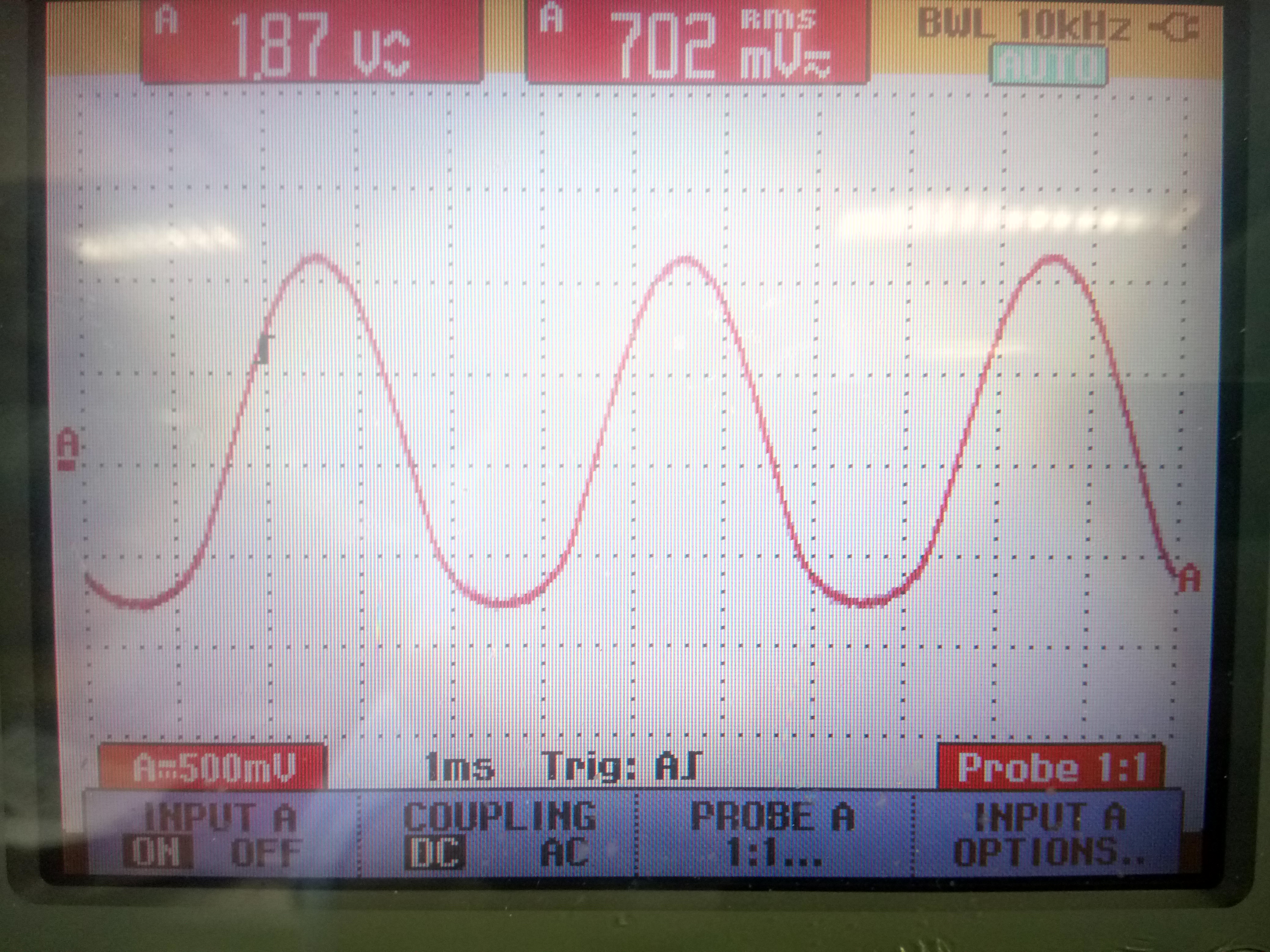
When I used the sinewave above, I could see on the oscilloscope that there was a distortion on the  input signal specially the negative peak.

My understanding that the ADC impedance input has to be very high (not 2.5K) and this is my causing this issue.

My question is for this microcontroller  or any microcontroller, do I need to put a amplifier (buffer) at the input of the ADC?

For now my signal conditioning circuit is just an resistive attenuator. 

Regards,

  • Can you provide a schematic of the circuit for your input signal? Is your AC signal going above and below GND as shown? In general there are several ways to compensate for a high impedance source. The first is to increase the sample time, The second is to add a capacitor at the ADC input. This has the additional affect of acting as a low pass filter.
  •  Hi Bob,

    Thank you for the reply.

    The signal is going above and below GND. This why added the offset (3.3v/2) through the voltage divider.

    When you want to measure a voltage in circuit you attached to it a volt-meter which has a high impedance  ( order of Mega Ohms such the Fluke brand) ( it is like is not physical connected to the circuit).

    In here the ADC input impedance is 2.5K which very low (only if I got this wrong). Are you saying that the low input impedance is not to blame?

    What is the value of the capacitor?

    In the circuit attached, I built a  4 x voltage dividers for four ADC channels. on strip board. I am testing only one channel to see if it will work.

  • No, the input impedance of the ADC is not to blame. The 2.5K Ohm (max) input impedance is between the input pin and the sample capacitor. Once the sample capacitor is charged, the leakage is 2uA or less.

    I think that the problem is you have an AC source with a low voltage swing below GND. Are the 1MOhm resisters really biasing your circuit to go from 0V to 3.3V? If so, then your AC source is floating and not centered at GND. What is the source impedance of the AC signal? If it is 50 Ohms, try using 1K resistors to bias the circuit instead of 1M.

    If the AC source is not floating, can you get the information you need with a half rectified signal? You should be able to determine frequency, positive amplitude, and phase. If not, you will need to isolate the signal from ground.
  • At start I am trying just to get the ADC to sample the sine wave and at the moment for testing I am just using a standard HP signal generator.
    If it work this will be connected to a real circuit thus it need a high input impedance so it doesn't disturb the circuit under test like a digital voltmeter. If I use 1K resistor, the ADC channel input impedance will be low and this is my affect the normal functioning of the circuit under test.

    The previous scope-shot is at the input of the ADC channel. Before I connect the output of the signal generator, the wave is a perfect sine, then when I connect the ADC channel, we get this distortion. You can see from the shot that the ADC input signal moving above and below 0.

    The test worked as expected for a DC voltage. Is This mean that the ADC input is not floating with 1Mohms voltage divider?

    By the way thank for taking interest in this topic.
  • I suspect that the signal from the signal generator is not floating. Does it have the ability to offset the signal by +1.5V so that the peaks are between 0V and 3.3V? You should not need any bias resistors. Will the real circuit provide an output between 0V and 3.3V?
  • Hi Bob,
    I think you are right. The scope-shot should show that the signal move above or below 1.6V ( Vref/2=3.3/2 V).
    The signal generator has a OFFSET function. I will try it on Monday.
    I used the voltage divider to provide this offset (+1.6V) but it seem, it is not working. In real circuit somehow I need to offset the AC voltage to be able to accommodate the range 0-3V. I though the voltage divider will do the tick.
  • A voltage divider that provides a bias will not solve the problem. If the signal to be sampled is bipolar (goes above and below ground) you need to either (1) offset the source to make the signal unipolar (between 0V and VDDA), (2) isolate the input signal such as using a isolation transformer or capacitively coupling. or (3) use an external bipolar ADC chip.
  • Hi 

    I added 1.5V DC offset using the signal generator thus signal go above or below 1.5V (0-3V) and the problem is gone.

    So the voltage divider in this case didn't help. It seems I can't avoid adding an Op-amp. I was thinking of using an op-amp  in summing  configuration with  1st input will be 1.5V DC and the 2nd input will be the signal (-1.5V to +1.5V).

    I will build the circuit and test it to see how it will behave.