


Part Number: TMS570LS1114
Other Parts Discussed in Thread: TPS74901, LM43603
Dears,
I have a problem about PLL of TMS570LS1114CZWTQQ1, the detail description as follows,
The communication anomalies will come after running for a period of time in my product (the problem time is irregular, sometimes a few minutes, sometimes a few hours) ,
the further analysis show that, the PLL failure of the TMS570LS1114CZWTQQ1 caused the Watchdog out of the timer, thereby being reset by the external watchdog.
Peripheral circuit:
Crystal oscillator: 10mhz±25ppm
1.2V LDO: 1.5V to 1.2V, TPS74901
3.3V DCDC: 5V to 3.3V, LM43603
watchdog: implemented by FPGA
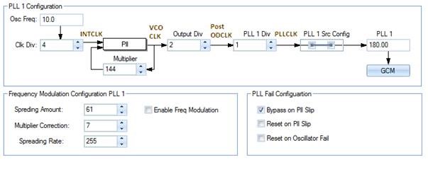
PLL Configuration:
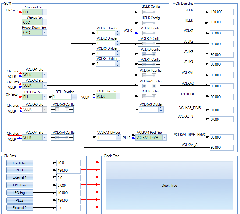
Clock Configuration:
I try to analysis the problem by the following methods for your reference:
1、Shielded watchdog reset signal, the problem occurs after the MCU is running for a period of time, at this time,
a) Observing the cycle of the debug indicator light controlled by GPIO , and find that the rollover period becomes longer, That means the MCU running slower
b) The MCU power supply and external crystal oscillator are normal viewed by oscilloscope
c) Then, turn off the external watchdog, the MCU's ECLK PIN is configured as a clock output (the normal output value is divided by 9 of VCLK1, which is 10MHz), as shown below. At this time the ECLK output clock is about 0.556MHz, so the VCLK1 clock is approximately 5MHz, so it is inferred that the PLL output is bypassed to 10MHz inside the chip.

d) Read the GLBSTAT , FBSLIP=1 and RFSLIP=1,
OSCFAIL = 0
the other bits are 0.
e) Read from fault register, no faults found
The above behavior shows that the MCU fails to detect the PLL, thereby switching the global clock to the chip's internal clock. And the problem time is irregular, sometimes a few minutes, sometimes a few hours.
- Based on the above configuration, the bypass function of the PLL is canceled and the MCU stops running when problem occurs and the register status cannot be read at this time.
