Part Number: EK-TM4C1294XL
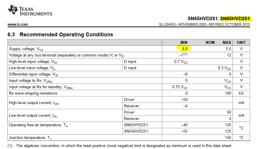
Other Parts Discussed in Thread: SN65HVD251, SN65HVD233
I'm having trouble using the CAN controller modules of the tm4c1294. I tried to modify the can example available for tm4c123 on tivaware, but I can't seem to make it work. I'm using 2 EK-TM4C1294XL, each one connected to a MCP2561 CAN transceiver on their CAN1 module (CAN1Rx PB0 and CAN1Tx PB1). My problem is, when I use an oscilloscope to watch the CAN1tx transmitting data, apparently no data is being transmied. CAN1Tx pin remains at 3V3 all the time. I get the message errors CAN_BUS_OFF and CAN_STATUS_EWARN. Below goes my code:
//*****************************************************************************
//
// can.c - Simple CAN example.
//
// Copyright (c) 2013-2017 Texas Instruments Incorporated. All rights reserved.
// Software License Agreement
//
// Texas Instruments (TI) is supplying this software for use solely and
// exclusively on TI's microcontroller products. The software is owned by
// TI and/or its suppliers, and is protected under applicable copyright
// laws. You may not combine this software with "viral" open-source
// software in order to form a larger program.
//
// THIS SOFTWARE IS PROVIDED "AS IS" AND WITH ALL FAULTS.
// NO WARRANTIES, WHETHER EXPRESS, IMPLIED OR STATUTORY, INCLUDING, BUT
// NOT LIMITED TO, IMPLIED WARRANTIES OF MERCHANTABILITY AND FITNESS FOR
// A PARTICULAR PURPOSE APPLY TO THIS SOFTWARE. TI SHALL NOT, UNDER ANY
// CIRCUMSTANCES, BE LIABLE FOR SPECIAL, INCIDENTAL, OR CONSEQUENTIAL
// DAMAGES, FOR ANY REASON WHATSOEVER.
//
// This is part of revision 2.1.4.178 of the DK-TM4C123G Firmware Package.
//
//*****************************************************************************
#include <stdint.h>
#include <stdbool.h>
#include <stdio.h>
#include <string.h>
#include "inc/hw_can.h"
#include "inc/hw_ints.h"
#include "inc/hw_memmap.h"
#include "driverlib/fpu.h"
#include "driverlib/can.h"
#include "driverlib/gpio.h"
#include "driverlib/pin_map.h"
#include "driverlib/rom.h"
#include "driverlib/sysctl.h"
#include "driverlib/uart.h"
#include "grlib/grlib.h"
#include "drivers/cfal96x64x16.h"
#include "utils/uartstdio.h"
#include "driverlib/interrupt.h"
//*****************************************************************************
//
//! \addtogroup example_list
//! <h1>CAN Example (can)</h1>
//!
//! This example application utilizes CAN to send characters back and forth
//! between two boards. It uses the UART to read / write the characters to
//! the UART terminal. It also uses the graphical display on the board to show
//! the last character transmited / received. Error handling is also included.
//!
//! CAN HARDWARE SETUP:
//!
//! To use this example you will need to hook up two DK-TM4C123G boards
//! together in a CAN network. This involves hooking the CANH screw terminals
//! together and the CANL terminals together. In addition 120ohm termination
//! resistors will need to be added to the edges of the network between CANH
//! and CANL. In the two board setup this means hooking a 120 ohm resistor
//! between CANH and CANL on both boards.
//!
//! See diagram below for visual. '---' represents wire.
//!
//! \verbatim
//! CANH--+--------------------------+--CANH
//! | |
//! .-. .-.
//! | |120ohm | |120ohm
//! | | | |
//! '-' '-'
//! | |
//! CANL--+--------------------------+--CANL
//! \endverbatim
//!
//! SOFTWARE SETUP:
//!
//! Once the hardware connections are setup connect both boards to the computer
//! via the In-Circuit Debug Interface USB port next to the graphical display.
//! Attach a UART terminal to each board configured 115,200 baud, 8-n-1 mode.
//!
//! Anything you type into one terminal will show up in the other terminal and
//! vice versa. The last character sent / received will also be displayed on
//! the graphical display on the board.
//
//*****************************************************************************
//*****************************************************************************
//
// A counter that keeps track of the number of times the TX & RX interrupt has
// occurred, which should match the number of messages that were transmitted /
// received.
//
//*****************************************************************************
volatile uint32_t g_ui32RXMsgCount = 0;
volatile uint32_t g_ui32TXMsgCount = 0;
//*****************************************************************************
//
// A flag for the interrupt handler to indicate that a message was received.
//
//*****************************************************************************
volatile bool g_bRXFlag = 0;
//*****************************************************************************
//
// A global to keep track of the error flags that have been thrown so they may
// be processed. This is necessary because reading the error register clears
// the flags, so it is necessary to save them somewhere for processing.
//
//*****************************************************************************
volatile uint32_t g_ui32ErrFlag = 0;
//*****************************************************************************
//
// CAN message Objects for data being sent / received
//
//*****************************************************************************
tCANMsgObject g_sCAN1RxMessage;
tCANMsgObject g_sCAN1TxMessage;
//*****************************************************************************
//
// Message Identifiers and Objects
// RXID is set to 0 so all messages are received
//
//*****************************************************************************
#define CAN1RXID 0
#define RXOBJECT 1
#define CAN1TXID 2
#define TXOBJECT 2
//*****************************************************************************
//
// Variables to hold character being sent / reveived
//
//*****************************************************************************
uint8_t g_ui8TXMsgData;
uint8_t g_ui8RXMsgData;
//*****************************************************************************
//
// Global context for text printed on graphics display
//
//*****************************************************************************
tContext g_sContext;
//*****************************************************************************
//
// The error routine that is called if the driver library encounters an error.
//
//*****************************************************************************
#ifdef DEBUG
void
__error__(char *pcFilename, uint32_t ui32Line)
{
}
#endif
//*****************************************************************************
//
// CAN 0 Interrupt Handler. It checks for the cause of the interrupt, and
// maintains a count of all messages that have been transmitted / received
//
//*****************************************************************************
void
CAN1IntHandler(void)
{
uint32_t ui32Status;
//
// Read the CAN interrupt status to find the cause of the interrupt
//
// CAN_INT_STS_CAUSE register values
// 0x0000 = No Interrupt Pending
// 0x0001-0x0020 = Number of message object that caused the interrupt
// 0x8000 = Status interrupt
// all other numbers are reserved and have no meaning in this system
//
ui32Status = CANIntStatus(CAN1_BASE, CAN_INT_STS_CAUSE);
//
// If this was a status interrupt acknowledge it by reading the CAN
// controller status register.
//
if(ui32Status == CAN_INT_INTID_STATUS)
{
//
// Read the controller status. This will return a field of status
// error bits that can indicate various errors. Refer to the
// API documentation for details about the error status bits.
// The act of reading this status will clear the interrupt.
//
ui32Status = CANStatusGet(CAN1_BASE, CAN_STS_CONTROL);
//
// Add ERROR flags to list of current errors. To be handled
// later, because it would take too much time here in the
// interrupt.
//
g_ui32ErrFlag |= ui32Status;
}
//
// Check if the cause is message object RXOBJECT, which we are using
// for receiving messages.
//
else if(ui32Status == RXOBJECT)
{
//
// Getting to this point means that the RX interrupt occurred on
// message object RXOBJECT, and the message reception is complete.
// Clear the message object interrupt.
//
CANIntClear(CAN1_BASE, RXOBJECT);
//
// Increment a counter to keep track of how many messages have been
// received. In a real application this could be used to set flags to
// indicate when a message is received.
//
g_ui32RXMsgCount++;
//
// Set flag to indicate received message is pending.
//
g_bRXFlag = true;
//
// Since a message was received, clear any error flags.
// This is done because before the message is received it triggers
// a Status Interrupt for RX complete. by clearing the flag here we
// prevent unnecessary error handling from happeneing
//
g_ui32ErrFlag = 0;
}
//
// Check if the cause is message object TXOBJECT, which we are using
// for transmitting messages.
//
else if(ui32Status == TXOBJECT)
{
//
// Getting to this point means that the TX interrupt occurred on
// message object TXOBJECT, and the message reception is complete.
// Clear the message object interrupt.
//
CANIntClear(CAN1_BASE, TXOBJECT);
//
// Increment a counter to keep track of how many messages have been
// transmitted. In a real application this could be used to set
// flags to indicate when a message is transmitted.
//
g_ui32TXMsgCount++;
//
// Since a message was transmitted, clear any error flags.
// This is done because before the message is transmitted it triggers
// a Status Interrupt for TX complete. by clearing the flag here we
// prevent unnecessary error handling from happeneing
//
g_ui32ErrFlag = 0;
}
//
// Otherwise, something unexpected caused the interrupt. This should
// never happen.
//
else
{
//
// Spurious interrupt handling can go here.
//
}
}
//*****************************************************************************
//
// Configure the UART and its pins. This must be called before UARTprintf().
//
//*****************************************************************************
void
ConfigureUART(void)
{
// Uart0
GPIOPinConfigure(GPIO_PA0_U0RX);
GPIOPinConfigure(GPIO_PA1_U0TX);
GPIOPinTypeUART(GPIO_PORTA_BASE, GPIO_PIN_0 | GPIO_PIN_1);
UARTConfigSetExpClk(UART0_BASE, 120000000, 115200,
(UART_CONFIG_WLEN_8 | UART_CONFIG_STOP_ONE |
UART_CONFIG_PAR_NONE));
UARTFIFODisable(UART0_BASE);
UARTEnable(UART0_BASE);
}
//*****************************************************************************
//
// Setup CAN1 to both send and receive at 500KHz.
// Interrupts on
// Use PE4 / PE5
//
//*****************************************************************************
void
InitCAN1(void)
{
//
// For this example CAN1 is used with RX and TX pins on port E4 and E5.
// GPIO port E needs to be enabled so these pins can be used.
//
SysCtlPeripheralEnable(SYSCTL_PERIPH_GPIOB);
while (!SysCtlPeripheralReady(SYSCTL_PERIPH_GPIOB));
//
// Configure the GPIO pin muxing to select CAN1 functions for these pins.
// This step selects which alternate function is available for these pins.
//
GPIOPinConfigure(GPIO_PB0_CAN1RX);
GPIOPinConfigure(GPIO_PB1_CAN1TX);
//
// Enable the alternate function on the GPIO pins. The above step selects
// which alternate function is available. This step actually enables the
// alternate function instead of GPIO for these pins.
//
GPIOPinTypeCAN(GPIO_PORTB_BASE, GPIO_PIN_0 | GPIO_PIN_1);
//
// The GPIO port and pins have been set up for CAN. The CAN peripheral
// must be enabled.
//
SysCtlPeripheralEnable(SYSCTL_PERIPH_CAN1);
while (!SysCtlPeripheralReady(SYSCTL_PERIPH_CAN1));
//
// Initialize the CAN controller
//
CANInit(CAN1_BASE);
//
// Set up the bit rate for the CAN bus. This function sets up the CAN
// bus timing for a nominal configuration. You can achieve more control
// over the CAN bus timing by using the function CANBitTimingSet() instead
// of this one, if needed.
// In this example, the CAN bus is set to 500 kHz.
//
CANBitRateSet(CAN1_BASE, 120000000, 500000);
//
// Enable interrupts on the CAN peripheral. This example uses static
// allocation of interrupt handlers which means the name of the handler
// is in the vector table of startup code.
//
CANIntRegister(CAN1_BASE, CAN1IntHandler);
CANIntEnable(CAN1_BASE, CAN_INT_MASTER | CAN_INT_ERROR | CAN_INT_STATUS);
//
// Enable the CAN interrupt on the processor (NVIC).
//
IntEnable(INT_CAN1);
//
// Enable the CAN for operation.
//
CANEnable(CAN1_BASE);
//
// Initialize a message object to be used for receiving CAN messages with
// any CAN ID. In order to receive any CAN ID, the ID and mask must both
// be set to 0, and the ID filter enabled.
//
g_sCAN1RxMessage.ui32MsgID = CAN1RXID;
g_sCAN1RxMessage.ui32MsgIDMask = 0;
g_sCAN1RxMessage.ui32Flags = MSG_OBJ_RX_INT_ENABLE | MSG_OBJ_USE_ID_FILTER;
g_sCAN1RxMessage.ui32MsgLen = sizeof(g_ui8RXMsgData);
//
// Now load the message object into the CAN peripheral. Once loaded the
// CAN will receive any message on the bus, and an interrupt will occur.
// Use message object RXOBJECT for receiving messages (this is not the
//same as the CAN ID which can be any value in this example).
//
CANMessageSet(CAN1_BASE, RXOBJECT, &g_sCAN1RxMessage, MSG_OBJ_TYPE_RX);
//
// Initialize the message object that will be used for sending CAN
// messages. The message will be 1 bytes that will contain the character
// received from the other controller. Initially it will be set to 0.
//
g_ui8TXMsgData = 0;
g_sCAN1TxMessage.ui32MsgID = CAN1TXID;
g_sCAN1TxMessage.ui32MsgIDMask = 0;
g_sCAN1TxMessage.ui32Flags = MSG_OBJ_TX_INT_ENABLE;
g_sCAN1TxMessage.ui32MsgLen = sizeof(g_ui8TXMsgData);
g_sCAN1TxMessage.pui8MsgData = (uint8_t *)&g_ui8TXMsgData;
}
//*****************************************************************************
//
// Can ERROR handling. When a message is received if there is an erro it is
// saved to g_ui32ErrFlag, the Error Flag Set. Below the flags are checked
// and cleared. It is left up to the user to add handling fuctionality if so
// desiered.
//
// For more information on the error flags please see the CAN section of the
// microcontroller datasheet.
//
// NOTE: you may experience errors during setup when only one board is powered
// on. This is caused by one board sending signals and there not being another
// board there to acknoledge it. Dont worry about these errors, they can be
// disregarded.
//
//*****************************************************************************
void
CANErrorHandler(void)
{
//
// CAN controller has entered a Bus Off state.
//
if(g_ui32ErrFlag & CAN_STATUS_BUS_OFF)
{
//
// Handle Error Condition here
//
// UARTprintf(" ERROR: CAN_STATUS_BUS_OFF \n");
debug_uart(" ERROR: CAN_STATUS_BUS_OFF \n", strlen(" ERROR: CAN_STATUS_BUS_OFF \n"));
//
// Clear CAN_STATUS_BUS_OFF Flag
//
g_ui32ErrFlag &= ~(CAN_STATUS_BUS_OFF);
}
//
// CAN controller error level has reached warning level.
//
if(g_ui32ErrFlag & CAN_STATUS_EWARN)
{
//
// Handle Error Condition here
//
//UARTprintf(" ERROR: CAN_STATUS_EWARN \n");
debug_uart(" ERROR: CAN_STATUS_EWARN \n", strlen(" ERROR: CAN_STATUS_EWARN \n"));
//
// Clear CAN_STATUS_EWARN Flag
//
g_ui32ErrFlag &= ~(CAN_STATUS_EWARN);
}
//
// CAN controller error level has reached error passive level.
//
if(g_ui32ErrFlag & CAN_STATUS_EPASS)
{
//
// Handle Error Condition here
//
//
// Clear CAN_STATUS_EPASS Flag
//
g_ui32ErrFlag &= ~(CAN_STATUS_EPASS);
}
//
// A message was received successfully since the last read of this status.
//
if(g_ui32ErrFlag & CAN_STATUS_RXOK)
{
//
// Handle Error Condition here
//
//
// Clear CAN_STATUS_RXOK Flag
//
g_ui32ErrFlag &= ~(CAN_STATUS_RXOK);
}
//
// A message was transmitted successfully since the last read of this
// status.
//
if(g_ui32ErrFlag & CAN_STATUS_TXOK)
{
//
// Handle Error Condition here
//
//
// Clear CAN_STATUS_TXOK Flag
//
g_ui32ErrFlag &= ~(CAN_STATUS_TXOK);
}
//
// This is the mask for the last error code field.
//
if(g_ui32ErrFlag & CAN_STATUS_LEC_MSK)
{
//
// Handle Error Condition here
//
//
// Clear CAN_STATUS_LEC_MSK Flag
//
g_ui32ErrFlag &= ~(CAN_STATUS_LEC_MSK);
}
//
// A bit stuffing error has occurred.
//
if(g_ui32ErrFlag & CAN_STATUS_LEC_STUFF)
{
//
// Handle Error Condition here
//
//
// Clear CAN_STATUS_LEC_STUFF Flag
//
g_ui32ErrFlag &= ~(CAN_STATUS_LEC_STUFF);
}
//
// A formatting error has occurred.
//
if(g_ui32ErrFlag & CAN_STATUS_LEC_FORM)
{
//
// Handle Error Condition here
//
//
// Clear CAN_STATUS_LEC_FORM Flag
//
g_ui32ErrFlag &= ~(CAN_STATUS_LEC_FORM);
}
//
// An acknowledge error has occurred.
//
if(g_ui32ErrFlag & CAN_STATUS_LEC_ACK)
{
//
// Handle Error Condition here
//
//
// Clear CAN_STATUS_LEC_ACK Flag
//
g_ui32ErrFlag &= ~(CAN_STATUS_LEC_ACK);
}
//
// The bus remained a bit level of 1 for longer than is allowed.
//
if(g_ui32ErrFlag & CAN_STATUS_LEC_BIT1)
{
//
// Handle Error Condition here
//
//
// Clear CAN_STATUS_LEC_BIT1 Flag
//
g_ui32ErrFlag &= ~(CAN_STATUS_LEC_BIT1);
}
//
// The bus remained a bit level of 0 for longer than is allowed.
//
if(g_ui32ErrFlag & CAN_STATUS_LEC_BIT0)
{
//
// Handle Error Condition here
//
//
// Clear CAN_STATUS_LEC_BIT0 Flag
//
g_ui32ErrFlag &= ~(CAN_STATUS_LEC_BIT0);
}
//
// A CRC error has occurred.
//
if(g_ui32ErrFlag & CAN_STATUS_LEC_CRC)
{
//
// Handle Error Condition here
//
//
// Clear CAN_STATUS_LEC_CRC Flag
//
g_ui32ErrFlag &= ~(CAN_STATUS_LEC_CRC);
}
//
// This is the mask for the CAN Last Error Code (LEC).
//
if(g_ui32ErrFlag & CAN_STATUS_LEC_MASK)
{
//
// Handle Error Condition here
//
//
// Clear CAN_STATUS_LEC_MASK Flag
//
g_ui32ErrFlag &= ~(CAN_STATUS_LEC_MASK);
}
//
// If there are any bits still set in g_ui32ErrFlag then something unhandled
// has happened. Print the value of g_ui32ErrFlag.
//
if(g_ui32ErrFlag !=0)
{
// UARTprintf(" Unhandled ERROR: %x \n",g_ui32ErrFlag);
debug_uart(" Unhandled ERROR: %x \n", strlen(" Unhandled ERROR: %x \n"));
}
}
void debug_uart(char * p, uint16_t length)
{
uint16_t x = 0;
while(x < length)
{
while (UARTBusy(UART0_BASE));
UARTCharPutNonBlocking(UART0_BASE, *p);
p++;
x++;
}
}
void sendCharUart0(unsigned char _c)
{
while (UARTBusy(UART0_BASE));
UARTCharPutNonBlocking(UART0_BASE, _c);
}
//*****************************************************************************
//
// Set up the system, initialize the UART, Graphics, and CAN. Then poll the
// UART for data. If there is any data send it, if there is any thing received
// print it out to the UART. If there are errors call the error handling
// function.
//
//*****************************************************************************
int
main(void)
{
//
// Enable lazy stacking for interrupt handlers. This allows floating-point
// instructions to be used within interrupt handlers, but at the expense of
// extra stack usage.
//
ROM_FPULazyStackingEnable();
//
// Set the clocking to run directly from the crystal.
//
uint32_t freq = SysCtlClockFreqSet(
(SYSCTL_XTAL_25MHZ | SYSCTL_OSC_MAIN | SYSCTL_USE_PLL |
SYSCTL_CFG_VCO_480), 120000000);
SysCtlPeripheralEnable(SYSCTL_PERIPH_UART0);
SysCtlPeripheralEnable(SYSCTL_PERIPH_UART3);
SysCtlPeripheralEnable(SYSCTL_PERIPH_GPIOA);
SysCtlPeripheralEnable(SYSCTL_PERIPH_GPIOD);
while (!SysCtlPeripheralReady(SYSCTL_PERIPH_UART3));
while (!SysCtlPeripheralReady(SYSCTL_PERIPH_UART0));
while (!SysCtlPeripheralReady(SYSCTL_PERIPH_GPIOA));
while (!SysCtlPeripheralReady(SYSCTL_PERIPH_GPIOD));
GPIOPinTypeGPIOOutput(GPIO_PORTD_BASE, GPIO_PIN_6);
GPIOPinWrite(GPIO_PORTD_BASE, GPIO_PIN_6, 0);
// Initialize the UART
ConfigureUART();
// Initialize CAN1
InitCAN1();
// Print welcome message
// UARTprintf("\nCAN Example App\n");
// UARTprintf("Type something to see it show up on the other terminal: \n\n");
debug_uart("\nCAN Example App\n", strlen("\nCAN Example App\n"));
debug_uart("Type something to see it show up on the other terminal: \n\n", strlen("Type something to see it show up on the other terminal: \n\n"));
// Poll UART for data, transmit across CAN when something is entered
while(1)
{
// If the flag is set, that means that the RX interrupt occurred and
// there is a message ready to be read from the CAN
if(g_bRXFlag)
{
//
// Reuse the same message object that was used earlier to configure
// the CAN for receiving messages. A buffer for storing the
// received data must also be provided, so set the buffer pointer
// within the message object.
//
g_sCAN1RxMessage.pui8MsgData = (uint8_t *) &g_ui8RXMsgData;
//
// Read the message from the CAN. Message object RXOBJECT is used
// (which is not the same thing as CAN ID). The interrupt clearing
// flag is not set because this interrupt was already cleared in
// the interrupt handler.
//
CANMessageGet(CAN1_BASE, RXOBJECT, &g_sCAN1RxMessage, 0);
//
// Clear the pending message flag so that the interrupt handler can
// set it again when the next message arrives.
//
g_bRXFlag = 0;
//
// Check to see if there is an indication that some messages were
// lost.
//
if(g_sCAN1RxMessage.ui32Flags & MSG_OBJ_DATA_LOST)
{
// UARTprintf("\nCAN message loss detected\n");
debug_uart("\nCAN message loss detected\n",
strlen("\nCAN message loss detected\n"));
}
// Print the received character to the UART terminal
// UARTprintf("%c", g_ui8RXMsgData);
sendCharUart0(g_ui8RXMsgData);
//
// Print the received character to the display,
// clear line with spaces
//
}
else
{
//
// Error Handling
//
if(g_ui32ErrFlag != 0)
{
CANErrorHandler();
}
//
// See if there is something new to transmit
//
while(UARTCharsAvail(UART0_BASE))
{
//
// Read the next character from the UART terminal
//
g_ui8TXMsgData = UARTCharGetNonBlocking(UART0_BASE);
// Send the CAN message using object number TXOBJECT (not the
// same thing as CAN ID, which is also TXOBJECT in this
// example). This function will cause the message to be
// transmitted right away.
CANMessageSet(CAN1_BASE, TXOBJECT, &g_sCAN1TxMessage,
MSG_OBJ_TYPE_TX);
}
}
}
}
Does anyone have any idea what could be going wrong?