This thread has been locked.

If you have a related question, please click the "Ask a related question" button in the top right corner. The newly created question will be automatically linked to this question.

RTOS/EK-TM4C1294XL: RTOS example VS Normal example

Part Number: EK-TM4C1294XL

Tool/software: TI-RTOS

Hi to you all

I am trying some examples (labs exercises) on the EK-TM4C1294XL.

I tried the standard examples from the CLP_Workbook.pdf and I also tried the RTOS examples for the same board. I did follow step by step labs instruction and it worked as it says in the lab manual which is great.

I want to use the standard supplied examples and add to it RTOS; i.e.  I start with RTOS project then import/modify as necessary for example USB bulk example and use it with RTOS template.

Is it possible to mix the two examples (after doing then necessary modification)?

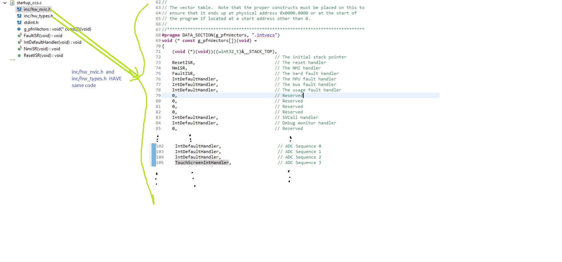
USB example uses Tx and Rx ISR routines which I don’t know what they are and in consequences how can I assign priority to them knowing that priority assignment is  an essential feature in RTOS.

In the past I tried touch screen Widget example with RTOS template. The project compiled successfully but nothing was happening. I believe that the LCD touch screen Widget uses interrupt (I don’t know which one) and this interrupt somehow the RTOS wasn’t aware of them.

By the way the RTOS examples were about turning ON/OFF a LED which was great and easy to learn RTOS but the next step after just a LED was calling.

Can anyone put some light on this please?


  • Hello Rab,

    I would suggest starting by working with the examples provided with the TI-RTOS for Tiva-C package. You can find them at [Install Path]\tirtos_tivac_2_16_01_14\tirtos_tivac_2_16_01_14_examples\TI\EK_TM4C1294XL

    The labs just get you going, they don't cover all the examples offered.

    I don't see a bulk example, but I would suggest starting with the usbserialdevice example and familiarize yourself with it and then add Bulk functionality by looking at how that is done with our TivaWare usb_dev_bulk example.
  • Hi Ralph
    Thank you for the quick reply as usual. :)
    I did both tasks you mentioned. I was just playing around USB bulk example ( firmware side and PC side). I want to take advantage of TI  RTOS not by turning ON/OFF led only but using other application such USB, ADC …
    As I said previously, I tried the Widget on its own and it did work ( in the example) but when I used the example with RTOS, it compiled successful but nothing happened (blank screen and doesn't response when I touch the screen).

  • Hello Rab,

    I am a little unclear due to the terminology. By widget do you mean the usb_dev_bulk TivaWare example? If so, how did you try to port to TI-RTOS? Which TI-RTOS example project did you use as a base for the porting?
  • Hi again
    The Widget is shape or form on the Lcd screen when you touch them they will do something.
    The widget example I tried was when you the screen, you will turn on or off the Led user on the board. It did work when I tried the example but when I imported it to Rtos, it didn't work
    The USB bulk example, I only tried the standard example. I haven't tried with Rtos. This is why I am asking this question before I may have a go
  • Hello Rab,

    Are you using the DK-TM4C129X then? Your E2E post title has EK-TM4C1294XL LaunchPad but that doesn't have an LCD built on it.
  • Hi Ralph
    I am using EK-TM4C1294XL. The LCD is an add-on. It works with other development boards too. The example provided was for the same board.
    What I mean, in RTOS template provided by the Code Composer Studio, the programmer has to define the interrupt service routine and define their priorities but for imported example like the once I mentioned before they come with their own interrupt service routine and you don't know what type of interrupt (hardware, software, idle...).
  • Hi Rab,

    Which RTOS and version are you using.

    Todd
  • Hello Todd,

    I am using TI RTOS (tirtos_tivac_2_16_01_14) . I tried to follow the " Intro to the TI-RTOS Kernel Workshop Lab Manual, Rev 4.00 – May 2015".
    For TIVA C series NON RTOS examples, I am using TivaWare_C_Series-2.1.4.178 and following the labs in " Creating IoT Solutions with the Tiva® C Series Connected LaunchPad Workshop " which is a student Guide and Lab Manual. The development board I am using is the EK-TM$C1294XL.

    Code Composer Studio version 7.4.0
  • The RTOS example used in the tutorial were using turning LED on/off to make things ewsy to understand as the author was concentrating on exposing the idea of the RTOS its self. I would love to see an example from real world application such using USB or LCD screen using RTOS application.
  • Hello Rab Boud,

    My understanding is you wish to port a non-RTOS example to TI-RTOS.

    The limiting factor is the Interrupt Service Routine (ISR) you mentioned before. The RTOS is not aware of the ISR and therefore it leads to undefined behavior.

    You will need to modify the non-RTOS example and find any code that modifies the NVIC or plugs an ISR function.

    You will then need to utilize the Hardware Interrupt (Hwi) Manager Proxy to create RTOS aware ISRs.

    Below I provide a pseudo code example of what you may expect:

    #include <ti/sysbios/hal/Hwi.h>
    
    void someFxn()
    {
        Hwi_Params hwiParams;
        Hwi_Handle hwiHandle;
    
        Hwi_Params_init(&hwiParams);
        hwiParams.priority = USB_INT_PRIORITY;
        hwiParams.arg = someArg;
    
        hwiHandle =  Hwi_create(USB_INT_NUMBER,
                                usbInterruptServiceRoutine,
                                &hwiParams,
                                NULL);
    
        if (hwiHandle == NULL)
        {
            /* An error occured! */
        }
    }
    
    void usbInterruptServiceRoutine(UArg someArg)
    {
        /* ISR code goes here */
    }

    Regards,
    Derrick

  • Hi Derrick,
    I am sorry I pressed by mistake the "This resolve my issue" button.
    Yes, you hit the nail on the head. That's exactly when I want to know.

    "You will need to modify the non-RTOS example and find any code that modifies the NVIC or plugs an ISR function." : do you mean find the code of the ISR in the Non-RTOS source code?

    "You will then need to utilize the Hardware Interrupt (Hwi) Manager Proxy to create RTOS aware ISRs." : I didn't get this.
    On the CCS IDE there is text based RTOS configuration tools to configure the .cfg for the TI RTOS and there is a kind of " manager" (when you open the .cfg file with XGCONF). I only know this 02 tools to allow you to configure the RTOS application such as adding and configuring SWIs, HWIs...

    For this one

    hwiHandle = Hwi_create(USB_INT_NUMBER,
    usbInterruptServiceRoutine,
    &hwiParams,
    NULL);
    I took the same approach by letting the RTOS knowing where is the ISR; I found the ISR code in the non-RTOS example then I used the code above to point toward this ISR.
    I didn't try the USB example but the LCD example.
  • Hi Rab Boud,

    rab boud said:
    Do you mean find the code of the ISR in the Non-RTOS source code?


    Yes, exactly.

    rab boud said:
    I didn't get this.
    On the CCS IDE there is text based RTOS configuration tools to configure the .cfg for the TI RTOS and there is a kind of " manager" (when you open the .cfg file with XGCONF). I only know this 02 tools to allow you to configure the RTOS application such as adding and configuring SWIs, HWIs...


    You're on the right track here. You will want to ensure your *.cfg file contains something like the following so that you can use Hwi.h in your application. This code blocked is commented with multiple options.

    /* ================ Hwi configuration ================ */
    var halHwi = xdc.useModule('ti.sysbios.hal.Hwi');
    var m3Hwi = xdc.useModule('ti.sysbios.family.arm.m3.Hwi');
    /*
     * Checks for Hwi (system) stack overruns while in the Idle loop.
     *
     * Pick one:
     *  - true (default)
     *      Checks the top word for system stack overflows during the idle loop and
     *      raises an Error if one is detected.
     *  - false
     *      Disabling the runtime check improves runtime performance and yields a
     *      reduced flash footprint.
     */
    //halHwi.checkStackFlag = true;
    halHwi.checkStackFlag = false;
    
    /*
     * The following options alter the system's behavior when a hardware exception
     * is detected.
     *
     * Pick one:
     *  - Hwi.enableException = true
     *      This option causes the default m3Hwi.excHandlerFunc function to fully
     *      decode an exception and dump the registers to the system console.
     *      This option raises errors in the Error module and displays the
     *      exception in ROV.
     *  - Hwi.enableException = false
     *      This option reduces code footprint by not decoding or printing the
     *      exception to the system console.
     *      It however still raises errors in the Error module and displays the
     *      exception in ROV.
     *  - Hwi.excHandlerFunc = null
     *      This is the most aggressive option for code footprint savings; but it
     *      can difficult to debug exceptions. It reduces flash footprint by
     *      plugging in a default while(1) trap when exception occur. This option
     *      does not raise an error with the Error module.
     */
    //m3Hwi.enableException = true;
    //m3Hwi.enableException = false;
    m3Hwi.excHandlerFunc = null;
    
    /*
     * Enable hardware exception generation when dividing by zero.
     *
     * Pick one:
     *  - 0 (default)
     *      Disables hardware exceptions when dividing by zero
     *  - 1
     *      Enables hardware exceptions when dividing by zero
     */
    m3Hwi.nvicCCR.DIV_0_TRP = 0;
    //m3Hwi.nvicCCR.DIV_0_TRP = 1;

    rab boud said:
    I took the same approach by letting the RTOS knowing where is the ISR; I found the ISR code in the non-RTOS example then I used the code above to point toward this ISR.

    This is the correct thing to do. However, you must also ensure any code in the non-RTOS example that initializes the ISR in anyway is removed as this will conflict with the Hwi Manager.

    Regards,
    Derrick

  • Hi and thank you for the reply.

    "However, you must also ensure any code in the non-RTOS example that initializes the ISR in anyway is removed "
    I hope that easy. I don't remember of the top of my head but when I was trying the LCD example and more interesting the Widget example where you touch on the LCD a button which will turn on/off the user LED.
    I couldn't find any information about which hardware interrupt that has been used.
    For example for a USB transmit interrupt or Receive interrupt, can you configure that in the *.cfg fille using text based or manager?

    Regards,
  • Hi Rab Boud,

    The "interrupt number" will correspond to an index in an interrupt table.

    Somewhere in the non-RTOS example will be a board support file which places the USB_ISR_Fxn() at a particular index. Additionally, you can refer to the Nested Vectored Interrupt Controller (NVIC) section of the datasheet. Based on the datasheet, I suspect you want interrupt 58 corresponding to USB MAC.

    rab boud said:
    For example for a USB transmit interrupt or Receive interrupt, can you configure that in the *.cfg fille using text based or manager?


    You will only need to modify you *.cfg file by pasting the aforementioned block of code (assuming you're not already using the Hwi Manager). All other changes will occur in your application.c file.

  •  Hello Derrick,

    "The "interrupt number" will correspond to an index in an interrupt table.

    Somewhere in the non-RTOS example will be a board support file which places the USB_ISR_Fxn() at a particular index. Additionally, you can refer to the Nested Vectored Interrupt Controller (NVIC) section of the datasheet. Based on the datasheet, I suspect you want interrupt 58 corresponding to USB MAC."

    Related to my LCD example, I found the NVIC table above.  In this case, the LCD  ISR is called TouchScreenIntHandler and it is attached to hardware interrupt ADC sequence 3 ( or vector number 65).  Is that what you meant? 

    If it is, so for RTOS example; do I need just  to replace the " TouchScreenIntHandler" in the NVIC table by IntDefaultHandler (as all the other once) and make *.cfg file point to TouchScreenIntHandler function?

    Also why the same code appear in two different files (hw_nvic.h and hw_types.h) . I though this will generate an error such " .. redefined..". Of course here it didn't but I couldn't understand why.

    Also the RTOS projects haven't got NVIC table file attached to it. I know I can define my own ISR in the *.cfg file but what about the others one that I didn't need. What is their default state?

    Regards,

  • Hello Rab Boud,

    That is correct.

    For the RTOS example you need to perform the Hwi_create using the TouchScreenIniHandler as such:

    #include <ti/sysbios/hal/Hwi.h>
    
    void someFxn()
    {
        Hwi_Params hwiParams;
        Hwi_Handle hwiHandle;
    
        Hwi_Params_init(&hwiParams);
        hwiParams.priority = LCD_INT_PRIORITY;
        hwiParams.arg = someArg;
    
        hwiHandle =  Hwi_create(65,
                                TouchScreenIntHandler,
                                &hwiParams,
                                NULL);
    
        if (hwiHandle == NULL)
        {
            /* An error occured! */
        }
    }
    
    void TouchScreenIntHandler(UArg someArg)
    {
        /* Pre-existing code stays the same... */
    }

    Not sure why the same code appears in hw_nvic.h and hw_types.h. Maybe someone from the TM4C can address that in a separate thread.

    rab boud said:
    Also the RTOS projects haven't got NVIC table file attached to it. I know I can define my own ISR in the *.cfg file but what about the others one that I didn't need. What is their default state?


    I wouldn't recommend trying to configure your ISR in the *.cfg file. Instead, use the C code I have provided above as an example. You will want to do this for each ISR the non-RTOS example requires.

    Also remember to remove any code from the non-RTOS example that will configure the interrupt controller. DO keep any code that enables the interrupts for a particular peripheral; for example, enabling the ADC Sequence 3 interrupt in the peripheral.

    Regards,
    Derrick

  • Hi Darrick and thank you for the useful info.

    LCD_INT_PRIORITY: is this a predefine value or the user has to set it?
    How to set the PRIORTIES or is there a good/bad way to set them up?

    "I wouldn't recommend trying to configure your ISR in the *.cfg file"

    In the RTSO example I was following, the author uses the *.cfg manager to configure HWIs, SWIs…
    I guess because it give more possibilities such setting stacks and heaps.


    For my example of the LCD, I believe, I have to dig up the interrupt service routine from somewhere as it is not showing on the project explorer. In the function main and after all the initialisations , there is only one function as shown below.

    while(1)
    {
    WidgetMessageQueueProcess();
    }

    This function will be called continuously (for ever) in the function main . I guess I can create a SWi using the *.cfg manager which will call this function and that resolve the issue.

    I noticed also in other example, the ISR code are not showing probably because it is part of a .lib file or a header file. How can you make RTOS point to them?
    I am sorry I got many questions but wanting to discover more is just human nature. :)
  • Rab,

    You can create the Hwi in the .cfg or during runtime. You decide which way you want to do it. You have examples of both now.

    Just to be clear, TI-RTOS creates and manages the vector table. Your application cannot provide or manage the vector table directly. You can make modifications to it via the Hwi module.

    We are not familiar with LCD code, so we cannot comment on it.

    Todd
  • "Just to be clear, TI-RTOS creates and manages the vector table. Your application cannot provide or manage the vector table directly. You can make modifications to it via the Hwi module."

    What I mean is the interrupts that are not used in non-RTOS applications are defined to point to  IntDefaultHandler in the NVIC table  by default. Is it the same case for RTOS templates or just left undefined. I know the user has to set their own ISR in .cfg file .

    "We are not familiar with LCD code, so we cannot comment on it"

    I gave that  as an example but in general if a function is called continuously which is not an ISR routine, how can you adapt that to work with RTOS application? 

    Also if the ISR routine is embedded in  *.lib (library file); how can you make the *.cfg file point to it?

    Regards


  • rab boud said:
    What I mean is the interrupts that are not used in non-RTOS applications are defined to point to  IntDefaultHandler in the NVIC table  by default. Is it the same case for RTOS templates or just left undefined. I know the user has to set their own ISR in .cfg file .


    The RTOS assigns a default handler and manages this internally. The application does not need to take any action.

    rab boud said:
    I gave that  as an example but in general if a function is called continuously which is not an ISR routine, how can you adapt that to work with RTOS application? 


    You should find the source code for this lib and include it in your application.

    Regards,
    Derrick

  • Thank you Derrick.

    At some point I will try to import the LCD example to RTOS  application by following these advice. I will let you know the results.

    Finger cross .

    Regards