This thread has been locked.

If you have a related question, please click the "Ask a related question" button in the top right corner. The newly created question will be automatically linked to this question.

CCS/TM4C123GH6PM: How to Communicate with SPI on Two TM4c123gh6PM boards on single PC

Part Number: TM4C123GH6PM

Tool/software: Code Composer Studio

Hello all,

How to implement SPI Communication using two TM4c123gh6pm boards (one as master and other as slave) on a single PC?

I have configured one Tm4c123gh6m board as master and other board as slave and written two c++ script using code composer studio.

i successfully transferred 10 bytes of data [1,2,3,4,5,6,7,8,9,10] from the master end and received at the slave side. 

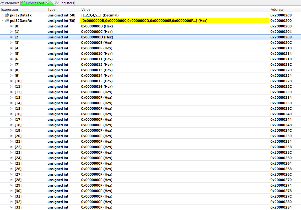
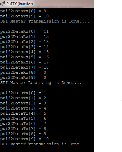
After that i am sending  10 byte of data [11,12,13,14,15,16,17,18,19,20] from slave then i am getting following 10 bytes of data  at master side

[11,12,13,14,15,16,17,18,0,0]. I am using PUTTY to monitor master and slave data using two serial windows on single PC.  

I am unable to receiving last two bytes of data properly at master side.

Here is my PUTTY serial windows

Please help me if anyone knows. It would great appreciation if you help others.  


  • Hello Neelakar,

    Have you checked via breakpoints if you are receiving the SPI data in your master but perhaps the issue is outputting to the terminal?

    Also, are these projects on LaunchPads? If so, can you provide the projects? I can review the code if so.
  • Hello Jacobi,

    Please find the master and slave code below.

    //*****************************************************************************
    //
    // ti_master.c - Example demonstrating how to configure SSI2 in TI master mode.
    //
    // Copyright (c) 2010-2017 Texas Instruments Incorporated.  All rights reserved.
    // Software License Agreement
    //
    // This is part of revision 2.1.4.178 of the Tiva Firmware Development Package.
    //
    //*****************************************************************************
    
    #include <stdbool.h>
    #include <stdint.h>
    #include "inc/hw_gpio.h"
    #include "inc/hw_ints.h"
    #include "inc/hw_nvic.h"
    #include "inc/hw_memmap.h"
    #include "inc/hw_types.h"
    #include "driverlib/debug.h"
    #include "driverlib/fpu.h"
    #include "driverlib/gpio.h"
    #include "driverlib/interrupt.h"
    #include "driverlib/pin_map.h"
    #include "driverlib/rom.h"
    #include "driverlib/pwm.h"
    #include "driverlib/sysctl.h"
    #include "driverlib/systick.h"
    #include "driverlib/uart.h"
    #include "utils/uartstdio.h"
    #include "driverlib/adc.h"
    #include "driverlib/timer.h"
    #include "math.h"
    #include "driverlib/ssi.h"
    #include "driverlib/qei.h"
    
    //*****************************************************************************
    //
    //! \addtogroup ssi_examples_list
    //! <h1>TI Master (ti_master)</h1>
    //!
    //! This example shows how to configure the SSI0 as TI Master.  The code will
    //! send three characters on the master Tx then poll the receive FIFO until
    //! 3 characters are received on the master Rx.
    //!
    //! This example uses the following peripherals and I/O signals.  You must
    //! review these and change as needed for your own board:
    //! - SSI2 peripheral
    //! - GPIO Port B peripheral (for SSI2 pins)
    //! - SSI2Clk - PB4
    //! - SSI2Fss - PB5
    //! - SSI2Rx  - PB6
    //! - SSI2Tx  - PB7
    //!
    //! The following UART signals are configured only for displaying console
    //! messages for this example.  These are not required for operation of I2C0.
    //! - UART0 peripheral
    //! - GPIO Port A peripheral (for UART0 pins)
    //! - UART0RX - PA0
    //! - UART0TX - PA1
    //!
    //! This example uses the following interrupt handlers.  To use this example
    //! in your own application you must add these interrupt handlers to your
    //! vector table.
    //! - None.
    //
    //*****************************************************************************
    
    //*****************************************************************************
    //
    // Number of bytes to send and receive.
    //
    //*****************************************************************************
    #define NUM_SSI_DATA            10
    //*****************************************************************************
    //
    // Global variables used in interrupt handler and the main loop.
    //
    //*****************************************************************************
    volatile unsigned long g_ulSSI2RXFF = 0, g_ulSSI2TXFF = 0;
    
    uint32_t pui32DataTx[NUM_SSI_DATA];
    uint32_t pui32DataRx[NUM_SSI_DATA];
    uint32_t ulDataTx0[NUM_SSI_DATA] = {1,2,3,4,5,6,7,8,9,10};
    uint32_t ulDataRx0[NUM_SSI_DATA] = {0};
    uint32_t ui32DataRx1[NUM_SSI_DATA] = {0};
    
    
    uint32_t ui32Index;
    uint32_t TxFlag = 0;
    uint32_t count = 0;
    uint32_t len = 0;
    //*****************************************************************************
    //
    // This function sets up UART0 to be used for a console to display information
    // as the example is running.
    //
    //*****************************************************************************
    void
    InitConsole(void)
    {
            //
            // Enable UART0 so that we can configure the clock.
            //
            SysCtlPeripheralEnable(SYSCTL_PERIPH_UART0);
    
            //
            // Enable GPIO port A which is used for UART0 pins.
            // TODO: change this to whichever GPIO port you are using.
            //
            SysCtlPeripheralEnable(SYSCTL_PERIPH_GPIOA);
    
            //
            // Configure the pin muxing for UART0 functions on port A0 and A1.
            // This step is not necessary if your part does not support pin muxing.
            // TODO: change this to select the port/pin you are using.
            //
            GPIOPinConfigure(GPIO_PA0_U0RX);
            GPIOPinConfigure(GPIO_PA1_U0TX);
    
            //
            // Use the internal 16MHz oscillator as the UART clock source.
            //
            UARTClockSourceSet(UART0_BASE, UART_CLOCK_PIOSC);
    
            //
            // Select the alternate (UART) function for these pins.
            // TODO: change this to select the port/pin you are using.
            //
            GPIOPinTypeUART(GPIO_PORTA_BASE, GPIO_PIN_0 | GPIO_PIN_1);
    
            //
            // Initialize the UART for console I/O.
            //
            UARTStdioConfig(0, 115200, 16000000);
    
    }
    //*****************************************************************************
    //
    // Configure SSI2 in Master TI mode.  This example will send out 10 bytes of
    // data, then wait for 3 bytes of data to come in.  This will all be done using
    // the interrupt method.
    //
    //*****************************************************************************
    void
    InitSSI2(void)
    {
       //
       // The SSI0 peripheral must be enabled for use.
       //
        SysCtlPeripheralEnable(SYSCTL_PERIPH_SSI2);
    
        //
        // For this example SSI2 is used with PortA[5:2].  The actual port and
        // pins used may be different on your part, consult the data sheet for
        // more information.  GPIO port A needs to be enabled so these pins can
        // be used.
        // TODO: change this to whichever GPIO port you are using.
        //
        SysCtlPeripheralEnable(SYSCTL_PERIPH_GPIOB);
    
        //
        //
        // Configure the pin muxing for SSI2 functions on port A2, A3, A4, and A5.
        // This step is not necessary if your part does not support pin muxing.
        // TODO: change this to select the port/pin you are using.
        //
    
        GPIOPinConfigure(GPIO_PB4_SSI2CLK);
        GPIOPinConfigure(GPIO_PB5_SSI2FSS);
        GPIOPinConfigure(GPIO_PB6_SSI2RX);
        GPIOPinConfigure(GPIO_PB7_SSI2TX);
    
        //
        // Configure the GPIO settings for the SSI pins.  This function also gives
        // control of these pins to the SSI hardware.  Consult the data sheet to
        // see which functions are allocated per pin.
        // The pins are assigned as follows:
        //      PB7 - SSI0Tx
        //      PB6 - SSI0Rx
        //      PB5 - SSI0Fss
        //      PB4 - SSI0CLK
        // TODO: change this to select the port/pin you are using.
        //
        GPIOPinTypeSSI(GPIO_PORTB_BASE,GPIO_PIN_7|GPIO_PIN_6|GPIO_PIN_5|GPIO_PIN_4);
    
    
        //
        // Configure and enable the SSI port for TI master mode.  Use SSI2, system
        // clock supply, master mode, 1MHz SSI frequency, and 8-bit data.
        //
        SSIConfigSetExpClk(SSI2_BASE, SysCtlClockGet(),SSI_FRF_MOTO_MODE_0,SSI_MODE_MASTER,10000, 8);
    
        //
        // Enable SSI2 module
        //
        SSIEnable(SSI2_BASE);
    
        SSIIntEnable(SSI2_BASE,SSI_RXTO);
    
        //
        // Read any residual data from the SSI port.  This makes sure the receive
        // FIFOs are empty, so we don't read any unwanted junk.  This is done here
        // because the TI SSI mode is full-duplex, which allows you to send and
        // receive at the same time.  The SSIDataGetNonBlocking function returns
        // "true" when data was returned, and "false" when no data was returned.
        // The "non-blocking" function checks if there is any data in the receive
        // FIFO and does not "hang" if there isn't.
        //
        while(SSIDataGetNonBlocking(SSI2_BASE, &pui32DataRx[0]))
        {
        }
    }
    
    //*****************************************************************************
    //
    // Interrupt handler for SSI2 peripheral in slave mode.  It reads the interrupt
    // status and if the interrupt is fired by a RX time out interrupt it reads the
    // SSI2 RX FIFO and increments a counter to tell the main loop that RX timeout
    // interrupt was fired.
    //
    //*****************************************************************************
    void SSI2IntHandler(void)
    {
        uint32_t ulStatus, ui32Index;
    
        //
        // Read interrupt status.
        //
        ulStatus = SSIIntStatus(SSI2_BASE, 1);
    
        //
        // Check the reason for the interrupt.
        //
        if((ulStatus & SSI_RXTO) == SSI_RXTO)
        {
    	//
    	// Clear the interrupt
    	//
            SSIIntClear(SSI2_BASE, SSI_RXTO);
    	
    	//
    	// Receive First byte from SSI2 Bus
    	//
            SSIDataGetNonBlocking(SSI2_BASE, &pui32DataRx[0]);
    
    	
    	//
    	// Check first byte is valid or not
    	//
            if(pui32DataRx[0] == 11)
            {
                //
                // Receive 10 bytes of data from SSI2 Bus
                //
                for(ui32Index = 1; ui32Index < NUM_SSI_DATA; ui32Index++)
                {
    	                //
                    // Receive the data using the "blocking" Get function. This function
                    // will wait until there is data in the receive FIFO before returning.
                    SSIDataGetNonBlocking(SSI2_BASE, &pui32DataRx[ui32Index]);
                }
    
    	        //
    	        // Wait until SSI2 is done receiving all the data in the receive FIFO.
    	        //
    		
                while(SSIBusy(SSI2_BASE))
                {
                }
    	    
    	   //
    	   // Receive falg indiactes the reception is complted
    	   //		
               g_ulSSI2RXFF++;
            }
    
    	
            else
            {
                while(SSIDataGetNonBlocking(SSI2_BASE, &ulDataRx0[0]))
                {
                }
    
    	    //
    	    // Clear the receiver FIFO
    	    //	
                for(ui32Index = 0; ui32Index < NUM_SSI_DATA; ui32Index++)
                {
                    pui32DataRx[ui32Index] = 0;
                }
    
                g_ulSSI2RXFF = 0;
            }
        }
    
        // Clear interrupts.
        //
        SSIIntClear(SSI2_BASE, ulStatus);
    
    }
    
    //*****************************************************************************
    //
    // This function is used to send multiple bytes of data over SSI2 bus
    //
    //*****************************************************************************
    void
    Send (uint32_t ulDataTx0[])
    {
        uint32_t ui32Index;
    
        //
        // Transmit 10 bytes of  data over SSI2 Bus
        //
        for(ui32Index = 0; ui32Index < NUM_SSI_DATA; ui32Index++)
        {
    		//
            // Load transmitted data into transmitted FIFO
            //
            pui32DataTx[ui32Index] = ulDataTx0[ui32Index];
    	
           //
           // Send the data using the "blocking" put function.  This function
           // will wait until there is room in the send FIFO before returning.
           // This allows you to assure that all the data you send makes it into
           // the send FIFO.
           //
           SSIDataPutNonBlocking(SSI2_BASE, pui32DataTx[ui32Index]);
    
           UARTprintf("pui32DataTx[%d] = %d\n",ui32Index,pui32DataTx[ui32Index]);
    
        }
    
        //
        // Wait until SSI2 is done transferring all the data in the transmit FIFO.
        //
        while(SSIBusy(SSI2_BASE))
        {
        }
    
        UARTprintf("SPI Master Transmission is Done....\n\n");
    }
    
    
    //*****************************************************************************
    //
    // This function is used to receive the multiple bytes of data and prints on to
    // the console screen
    //
    //*****************************************************************************
    void
    Ask (void)
    {
        uint32_t count = 0;
    
        if(g_ulSSI2RXFF)
        {
          for(count = 0; count < NUM_SSI_DATA; count++)
          {
              //
              // Display the data that SSI2 received.
              //
              UARTprintf("pui32DataRx[%d] = %d \n", count,pui32DataRx[count]);
           }
    
          UARTprintf("SPI Master Receiving is Done....\n\n");
    
          g_ulSSI2RXFF = 0;
        }
    
    }
    
    
    //*****************************************************************************
    //
    // Main function entry starts here
    //
    //*****************************************************************************
    int
    main(void)
    {
        //
        // Set the clocking to run directly from the external crystal/oscillator.
        // TODO: The SYSCTL_XTAL_ value must be changed to match the value of the
        // crystal on your board.
        //
    
        SysCtlClockSet(SYSCTL_SYSDIV_4 | SYSCTL_USE_OSC | SYSCTL_OSC_MAIN |
                       SYSCTL_XTAL_16MHZ);
    
    
        //
        // Set up the serial console to use for displaying messages.  This is
        // just for this example program and is not needed for SSI operation.
        //
        InitConsole();
        //
        // Display the setup on the console.
        //
        UARTprintf("SSI ->\n");
        UARTprintf("  Mode: TI\n");
        UARTprintf("  Data: 8-bit\n\n");
    
        InitSSI2();
        IntEnable(INT_SSI2);
        IntMasterEnable();
    
    //    //
    //    // This loop is to find length of an array
    //    //
    //    for(count = 0; ulDataTx0[count] !='\0';count++)
    //    {
    //        len++;
    //    }
    
        while(1)
        {
          Send(ulDataTx0);
          SysCtlDelay(200000);
          Ask();
    
        }
    
        }


    //*****************************************************************************
    //
    // ti_Slave.c - Example demonstrating how to configure SSI2 in TI master mode.
    //
    // Copyright (c) 2010-2017 Texas Instruments Incorporated.  All rights reserved.
    // Software License Agreement
    //
    // This is part of revision 2.1.4.178 of the Tiva Firmware Development Package.
    //
    //*****************************************************************************
    
    #include <stdbool.h>
    #include <stdint.h>
    #include "inc/hw_gpio.h"
    #include "inc/hw_ints.h"
    #include "inc/hw_nvic.h"
    #include "inc/hw_memmap.h"
    #include "inc/hw_types.h"
    #include "driverlib/debug.h"
    #include "driverlib/fpu.h"
    #include "driverlib/gpio.h"
    #include "driverlib/interrupt.h"
    #include "driverlib/pin_map.h"
    #include "driverlib/rom.h"
    #include "driverlib/pwm.h"
    #include "driverlib/sysctl.h"
    #include "driverlib/systick.h"
    #include "driverlib/uart.h"
    #include "utils/uartstdio.h"
    #include "driverlib/adc.h"
    #include "driverlib/timer.h"
    #include "math.h"
    #include "driverlib/ssi.h"
    #include "driverlib/qei.h"
    
    //*****************************************************************************
    //
    //! \addtogroup ssi_examples_list
    //! <h1>TI Master (ti_master)</h1>
    //!
    //! This example shows how to configure the SSI0 as TI Master.  The code will
    //! send three characters on the master Tx then poll the receive FIFO until
    //! 3 characters are received on the master Rx.
    //!
    //! This example uses the following peripherals and I/O signals.  You must
    //! review these and change as needed for your own board:
    //! - SSI2 peripheral
    //! - GPIO Port B peripheral (for SSI2 pins)
    //! - SSI2Clk - PB4
    //! - SSI2Fss - PB5
    //! - SSI2Rx  - PB6
    //! - SSI2Tx  - PB7
    //!
    //! The following UART signals are configured only for displaying console
    //! messages for this example.  These are not required for operation of I2C0.
    //! - UART0 peripheral
    //! - GPIO Port A peripheral (for UART0 pins)
    //! - UART0RX - PA0
    //! - UART0TX - PA1
    //!
    //! This example uses the following interrupt handlers.  To use this example
    //! in your own application you must add these interrupt handlers to your
    //! vector table.
    //! - None.
    //
    //*****************************************************************************
    
    //*****************************************************************************
    //
    // Number of bytes to send and receive.
    //
    //*****************************************************************************
    #define NUM_SSI_DATA            10
    //*****************************************************************************
    //
    // Global variables used in interrupt handler and the main loop.
    //
    //*****************************************************************************
    volatile unsigned long g_ulSSI2RXFF = 0, g_ulSSI2TXFF = 0;
    
    uint32_t pui32DataTx[NUM_SSI_DATA];
    uint32_t pui32DataRx[NUM_SSI_DATA];
    uint32_t g_ulDataTx0[NUM_SSI_DATA];
    uint32_t ulDataRx0[NUM_SSI_DATA];
    
    uint32_t ui32Index;


    uint32_t SSITxFlag = 0;
    
    //*****************************************************************************
    
    //
    // This function sets up UART0 to be used for a console to display information
    // as the example is running.
    //
    //*****************************************************************************
    void
    InitConsole(void)
    {
            //
            // Enable UART0 so that we can configure the clock.
            //
            SysCtlPeripheralEnable(SYSCTL_PERIPH_UART0);
    
            //
            // Enable GPIO port A which is used for UART0 pins.
            // TODO: change this to whichever GPIO port you are using.
            //
            SysCtlPeripheralEnable(SYSCTL_PERIPH_GPIOA);
    
            //
            // Configure the pin muxing for UART0 functions on port A0 and A1.
            // This step is not necessary if your part does not support pin muxing.
            // TODO: change this to select the port/pin you are using.
            //
            GPIOPinConfigure(GPIO_PA0_U0RX);
            GPIOPinConfigure(GPIO_PA1_U0TX);
    
            //
            // Use the internal 16MHz oscillator as the UART clock source.
            //
            UARTClockSourceSet(UART0_BASE, UART_CLOCK_PIOSC);
    
            //
            // Select the alternate (UART) function for these pins.
            // TODO: change this to select the port/pin you are using.
            //
            GPIOPinTypeUART(GPIO_PORTA_BASE, GPIO_PIN_0 | GPIO_PIN_1);
    
            //
            // Initialize the UART for console I/O.
            //
            UARTStdioConfig(0, 115200, 16000000);
    
    }
    
    //*****************************************************************************
    //
    // Configure SSI2 in Slave TI mode.  This example will send out 10 bytes of
    // data, then wait for 3 bytes of data to come in.  This will all be done using
    // the interrupt method.
    //
    //*****************************************************************************
    
    void
    InitSSI2(void)
    {
       //
       // The SSI0 peripheral must be enabled for use.
       //
        SysCtlPeripheralEnable(SYSCTL_PERIPH_SSI2);
    
        //
        // For this example SSI2 is used with PortA[5:2].  The actual port and
        // pins used may be different on your part, consult the data sheet for
        // more information.  GPIO port A needs to be enabled so these pins can
        // be used.
        // TODO: change this to whichever GPIO port you are using.
        //
        SysCtlPeripheralEnable(SYSCTL_PERIPH_GPIOB);
    
        //
        //
        // Configure the pin muxing for SSI2 functions on port A2, A3, A4, and A5.
        // This step is not necessary if your part does not support pin muxing.
        // TODO: change this to select the port/pin you are using.
        //
    
        GPIOPinConfigure(GPIO_PB4_SSI2CLK);
        GPIOPinConfigure(GPIO_PB5_SSI2FSS);
        GPIOPinConfigure(GPIO_PB6_SSI2RX);
        GPIOPinConfigure(GPIO_PB7_SSI2TX);
    
        //
        // Configure the GPIO settings for the SSI pins.  This function also gives
        // control of these pins to the SSI hardware.  Consult the data sheet to
        // see which functions are allocated per pin.
        // The pins are assigned as follows:
        //      PB7 - SSI0Tx
        //      PB6 - SSI0Rx
        //      PB5 - SSI0Fss
        //      PB4 - SSI0CLK
        // TODO: change this to select the port/pin you are using.
        //
        GPIOPinTypeSSI(GPIO_PORTB_BASE,GPIO_PIN_7|GPIO_PIN_6|GPIO_PIN_5|GPIO_PIN_4);
       // GPIOPadConfigSet(GPIO_PORTB_BASE,GPIO_PIN_7,GPIO_STRENGTH_8MA,GPIO_PIN_TYPE_STD_WPU);
    
        //
        // Configure and enable the SSI port for TI master mode.  Use SSI2, system
        // clock supply, master mode, 1MHz SSI frequency, and 8-bit data.
        //
        SSIConfigSetExpClk(SSI2_BASE, SysCtlClockGet(),SSI_FRF_MOTO_MODE_0,SSI_MODE_SLAVE,10000, 8);
    
        //
        // Enable SSI2 module
        //
        SSIEnable(SSI2_BASE);
    
        SSIIntEnable(SSI2_BASE, SSI_RXFF);
    
        //
        // Read any residual data from the SSI port.  This makes sure the receive
        // FIFOs are empty, so we don't read any unwanted junk.  This is done here
        // because the TI SSI mode is full-duplex, which allows you to send and
        // receive at the same time.  The SSIDataGetNonBlocking function returns
        // "true" when data was returned, and "false" when no data was returned.
        // The "non-blocking" function checks if there is any data in the receive
        // FIFO and does not "hang" if there isn't.
        //
        while(SSIDataGetNonBlocking(SSI2_BASE, &ulDataRx0[0]))
        {
        }
    }
    
    
    //*****************************************************************************
    //
    // Interrupt handler for SSI2 peripheral in slave mode.  It reads the interrupt
    // status and if the interrupt is fired by a RX time out interrupt it reads the
    // SSI2 RX FIFO and increments a counter to tell the main loop that RX timeout
    // interrupt was fired.
    //
    //*****************************************************************************
    void SSI2IntHandler(void)
    {
        uint32_t ulStatus,ui32Index;
    
        //
        // Read interrupt status.
        //
        ulStatus = SSIIntStatus(SSI2_BASE, 1);
    
      //
        // Check the reason for the interrupt.
        //
        if((ulStatus & SSI_RXFF) == SSI_RXFF)
        {
    	//
    	// Clear the interrupt
    	//
    		SSIIntClear(SSI2_BASE, SSI_RXFF);
    
    	//
    	// Receive First byte from SSI2 Bus
    	//
    		SSIDataGet(SSI2_BASE, &pui32DataRx[0]);
    	//
    	// Check first byte is valid or not
    	//
    		if(pui32DataRx[0] == 1)
    		{
    		    //
    		    // Receive 10 bytes of data.
    		    //
    		    for(ui32Index = 1; ui32Index < NUM_SSI_DATA; ui32Index++)
    		    {
                    //
                    // Receive the data using the "blocking" Get function. This function
                    // will wait until there is data in the receive FIFO before returning.
                    //
    		        SSIDataGet(SSI2_BASE, &pui32DataRx[ui32Index]);
    
                }
    
    	        //
    	        // Wait until SSI2 is done receiving all the data in the receive FIFO.
    	        //
    	        while(SSIBusy(SSI2_BASE))
    	        {
    	        }
    
    	   //
    	   // Receive falg indiactes the reception is complted
    	   //	
    	        g_ulSSI2RXFF++;
    
    		}
    		else
    		{
    		    while(SSIDataGetNonBlocking(SSI2_BASE, &ulDataRx0[0]))
    		    {
    		    }
    
    	    //
    	    // Clear the receiver FIFO
    	    //	
    		    for(ui32Index = 0; ui32Index < NUM_SSI_DATA; ui32Index++)
    		    {
    		        pui32DataRx[ui32Index] = 0;
    		    }
    		    g_ulSSI2RXFF = 0;
    		}
        }
    
        // Clear interrupts.
        //
        SSIIntClear(SSI2_BASE, ulStatus);
    }
    
    
    //*****************************************************************************
    //
    // This function is used to send multiple bytes of data over SSI2 bus
    //
    //*****************************************************************************
    void
    Send (uint32_t DataTx[])
    {
        uint32_t ui32Index;
    
        for(ui32Index = 0; ui32Index < NUM_SSI_DATA; ui32Index++)
        {
           //
           // Load received data into transmit buffer
           //
           pui32DataTx[ui32Index] = DataTx[ui32Index];
        }
    
    
        for(ui32Index = 0; ui32Index < NUM_SSI_DATA; ui32Index++)
        {
            //
            // Send the data using the "blocking" put function.  This function
            // will wait until there is room in the send FIFO before returning.
            // This allows you to assure that all the data you send makes it into
            // the send FIFO.
            //
            SSIDataPut(SSI2_BASE, pui32DataTx[ui32Index]);
    
            UARTprintf("pui32DataTx[%d] = %d \n",ui32Index ,pui32DataTx[ui32Index]);
    
        }
    
        while(SSIBusy(SSI2_BASE))
        {
        }
    
    	UARTprintf("SPI Slave Sent Data\n\n");
    }


    //*****************************************************************************
    //
    // This function is used to receive the multiple bytes of data and prints on to
    // the console screen
    //
    //*****************************************************************************
    void
    Ask (void)
    {
        uint32_t count = 0;
    
        if(g_ulSSI2RXFF)
        {
            for(count = 0; count < NUM_SSI_DATA; count++)
            {
                g_ulDataTx0[count]  =  pui32DataRx[count] + 10;
            //
            // Display the data that SSI0 received.
            //
            UARTprintf("pui32DataRx[%d] = %d \n", count,pui32DataRx[count]);
            }
            UARTprintf("SPI Slave Receiving is Done....\n\n");
         //   g_ulSSI2RXFF = 0;
        }
    }
    
    //*****************************************************************************
    //
    // Main function entry starts here
    //
    //*****************************************************************************
    int
    main(void)
    {
    
            //
            // Set the clocking to run directly from the external crystal/oscillator.
            SysCtlClockSet(SYSCTL_SYSDIV_4 | SYSCTL_USE_OSC | SYSCTL_OSC_MAIN |
                           SYSCTL_XTAL_16MHZ);
    
    
            InitConsole();
            
            UARTprintf("\n\nSSI ->\n");
            UARTprintf("  Mode: TI\n");
            UARTprintf("  Data: 8-bit\n\n");
    
            InitSSI2();
            IntEnable(INT_SSI2);
    		IntMasterEnable();
    
    
            while(1)
            {
                Ask();
                if(g_ulSSI2RXFF)
                {
                Send(g_ulDataTx0);
                g_ulSSI2RXFF = 0;
                }
            }
    
    }
    

  • Hi Jacobi,

    Can we able to implement SPI Communication using TM4C123GH6PM ( one as master and other as slave ) borads ?
  • Hello Neelakar,

    I ran your code and did a little debugging to uncover the core issue. You are overrunning the RX FIFO.

    The RX FIFO is 8 bytes deep, and you are trying to fill it with 10 bytes of data.

    Using breakpoints, you can clearly see the Overrun interrupt flag for SSI2 is set via CCS View -> Registers -> SSI2.

    I attempted to remedy that issue by using SSI_RXFF instead of SSI_RXTO for your Interrupt, however that exposes flaws with your program methodology that are application specific.

    When using the RXFF interrupt, the checks you run for the FIFO contents cause the data to be cleared as multiple interrupts are required to process your data.

    I had to make a number of modifications to get the desired results, but they aren't really all that great. I think you need to re-think your approach in terms of how you process the received data. But in any case, hopefully this will get you going correctly, I am posting the modified  code for the master side (didn't have to change slave side) below:

    //*****************************************************************************
    //
    // ti_master.c - Example demonstrating how to configure SSI2 in TI master mode.
    //
    // Copyright (c) 2010-2017 Texas Instruments Incorporated.  All rights reserved.
    // Software License Agreement
    //
    // This is part of revision 2.1.4.178 of the Tiva Firmware Development Package.
    //
    //*****************************************************************************
    
    #include <stdbool.h>
    #include <stdint.h>
    #include "inc/hw_gpio.h"
    #include "inc/hw_ints.h"
    #include "inc/hw_nvic.h"
    #include "inc/hw_memmap.h"
    #include "inc/hw_types.h"
    #include "driverlib/debug.h"
    #include "driverlib/fpu.h"
    #include "driverlib/gpio.h"
    #include "driverlib/interrupt.h"
    #include "driverlib/pin_map.h"
    #include "driverlib/rom.h"
    #include "driverlib/pwm.h"
    #include "driverlib/sysctl.h"
    #include "driverlib/systick.h"
    #include "driverlib/uart.h"
    #include "utils/uartstdio.h"
    #include "driverlib/adc.h"
    #include "driverlib/timer.h"
    #include "math.h"
    #include "driverlib/ssi.h"
    #include "driverlib/qei.h"
    
    //*****************************************************************************
    //
    //! \addtogroup ssi_examples_list
    //! <h1>TI Master (ti_master)</h1>
    //!
    //! This example shows how to configure the SSI0 as TI Master.  The code will
    //! send three characters on the master Tx then poll the receive FIFO until
    //! 3 characters are received on the master Rx.
    //!
    //! This example uses the following peripherals and I/O signals.  You must
    //! review these and change as needed for your own board:
    //! - SSI2 peripheral
    //! - GPIO Port B peripheral (for SSI2 pins)
    //! - SSI2Clk - PB4
    //! - SSI2Fss - PB5
    //! - SSI2Rx  - PB6
    //! - SSI2Tx  - PB7
    //!
    //! The following UART signals are configured only for displaying console
    //! messages for this example.  These are not required for operation of I2C0.
    //! - UART0 peripheral
    //! - GPIO Port A peripheral (for UART0 pins)
    //! - UART0RX - PA0
    //! - UART0TX - PA1
    //!
    //! This example uses the following interrupt handlers.  To use this example
    //! in your own application you must add these interrupt handlers to your
    //! vector table.
    //! - None.
    //
    //*****************************************************************************
    
    //*****************************************************************************
    //
    // Number of bytes to send and receive.
    //
    //*****************************************************************************
    #define NUM_SSI_DATA            10
    //*****************************************************************************
    //
    // Global variables used in interrupt handler and the main loop.
    //
    //*****************************************************************************
    volatile unsigned long g_ulSSI2RXFF = 0, g_ulSSI2TXFF = 0;
    
    uint32_t pui32DataTx[NUM_SSI_DATA];
    uint32_t pui32DataRx[NUM_SSI_DATA];
    uint32_t ulDataTx0[NUM_SSI_DATA] = {1,2,3,4,5,6,7,8,9,10};
    uint32_t ulDataRx0[NUM_SSI_DATA] = {0};
    uint32_t ui32DataRx1[NUM_SSI_DATA] = {0};
    
    volatile uint32_t g_ui32ExpectedFIFOData = 11;
    volatile uint32_t g_ui32Index = 0;
    
    uint32_t TxFlag = 0;
    uint32_t count = 0;
    uint32_t len = 0;
    //*****************************************************************************
    //
    // This function sets up UART0 to be used for a console to display information
    // as the example is running.
    //
    //*****************************************************************************
    void
    InitConsole(void)
    {
    	//
    	// Enable UART0 so that we can configure the clock.
    	//
    	SysCtlPeripheralEnable(SYSCTL_PERIPH_UART0);
    
    	//
    	// Enable GPIO port A which is used for UART0 pins.
    	// TODO: change this to whichever GPIO port you are using.
    	//
    	SysCtlPeripheralEnable(SYSCTL_PERIPH_GPIOA);
    
    	//
    	// Configure the pin muxing for UART0 functions on port A0 and A1.
    	// This step is not necessary if your part does not support pin muxing.
    	// TODO: change this to select the port/pin you are using.
    	//
    	GPIOPinConfigure(GPIO_PA0_U0RX);
    	GPIOPinConfigure(GPIO_PA1_U0TX);
    
    	//
    	// Use the internal 16MHz oscillator as the UART clock source.
    	//
    	UARTClockSourceSet(UART0_BASE, UART_CLOCK_PIOSC);
    
    	//
    	// Select the alternate (UART) function for these pins.
    	// TODO: change this to select the port/pin you are using.
    	//
    	GPIOPinTypeUART(GPIO_PORTA_BASE, GPIO_PIN_0 | GPIO_PIN_1);
    
    	//
    	// Initialize the UART for console I/O.
    	//
    	UARTStdioConfig(0, 115200, 16000000);
    
    }
    //*****************************************************************************
    //
    // Configure SSI2 in Master TI mode.  This example will send out 10 bytes of
    // data, then wait for 3 bytes of data to come in.  This will all be done using
    // the interrupt method.
    //
    //*****************************************************************************
    void
    InitSSI2(void)
    {
    	//
    	// The SSI0 peripheral must be enabled for use.
    	//
    	SysCtlPeripheralEnable(SYSCTL_PERIPH_SSI2);
    
    	//
    	// For this example SSI2 is used with PortA[5:2].  The actual port and
    	// pins used may be different on your part, consult the data sheet for
    	// more information.  GPIO port A needs to be enabled so these pins can
    	// be used.
    	// TODO: change this to whichever GPIO port you are using.
    	//
    	SysCtlPeripheralEnable(SYSCTL_PERIPH_GPIOB);
    
    	//
    	//
    	// Configure the pin muxing for SSI2 functions on port A2, A3, A4, and A5.
    	// This step is not necessary if your part does not support pin muxing.
    	// TODO: change this to select the port/pin you are using.
    	//
    
    	GPIOPinConfigure(GPIO_PB4_SSI2CLK);
    	GPIOPinConfigure(GPIO_PB5_SSI2FSS);
    	GPIOPinConfigure(GPIO_PB6_SSI2RX);
    	GPIOPinConfigure(GPIO_PB7_SSI2TX);
    
    	//
    	// Configure the GPIO settings for the SSI pins.  This function also gives
    	// control of these pins to the SSI hardware.  Consult the data sheet to
    	// see which functions are allocated per pin.
    	// The pins are assigned as follows:
    	//      PB7 - SSI0Tx
    	//      PB6 - SSI0Rx
    	//      PB5 - SSI0Fss
    	//      PB4 - SSI0CLK
    	// TODO: change this to select the port/pin you are using.
    	//
    	GPIOPinTypeSSI(GPIO_PORTB_BASE,GPIO_PIN_7|GPIO_PIN_6|GPIO_PIN_5|GPIO_PIN_4);
    
    
    	//
    	// Configure and enable the SSI port for TI master mode.  Use SSI2, system
    	// clock supply, master mode, 1MHz SSI frequency, and 8-bit data.
    	//
    	SSIConfigSetExpClk(SSI2_BASE, SysCtlClockGet(),SSI_FRF_MOTO_MODE_0,SSI_MODE_MASTER,10000, 8);
    
    	//
    	// Enable SSI2 module
    	//
    	SSIEnable(SSI2_BASE);
    
    	SSIIntEnable(SSI2_BASE,SSI_RXFF);
    
    	//
    	// Read any residual data from the SSI port.  This makes sure the receive
    	// FIFOs are empty, so we don't read any unwanted junk.  This is done here
    	// because the TI SSI mode is full-duplex, which allows you to send and
    	// receive at the same time.  The SSIDataGetNonBlocking function returns
    	// "true" when data was returned, and "false" when no data was returned.
    	// The "non-blocking" function checks if there is any data in the receive
    	// FIFO and does not "hang" if there isn't.
    	//
    	while(SSIDataGetNonBlocking(SSI2_BASE, &pui32DataRx[0]))
    	{
    	}
    }
    
    //*****************************************************************************
    //
    // Interrupt handler for SSI2 peripheral in slave mode.  It reads the interrupt
    // status and if the interrupt is fired by a RX time out interrupt it reads the
    // SSI2 RX FIFO and increments a counter to tell the main loop that RX timeout
    // interrupt was fired.
    //
    //*****************************************************************************
    void SSI2IntHandler(void)
    {
    	uint32_t ulStatus, ui32Index;
    
    	//
    	// Read interrupt status.
    	//
    	ulStatus = SSIIntStatus(SSI2_BASE, 1);
    
    	//
    	// Check the reason for the interrupt.
    	//
    	if((ulStatus & SSI_RXFF) == SSI_RXFF)
    	{
    		//
    		// Clear the interrupt
    		//
    		SSIIntClear(SSI2_BASE, SSI_RXFF);
    
    		//
    		// Receive First byte from SSI2 Bus
    		//
    		SSIDataGetNonBlocking(SSI2_BASE, &pui32DataRx[g_ui32Index++]);
    
    
    		//
    		// Check first byte is valid or not
    		//
    		if(pui32DataRx[g_ui32Index-1] == g_ui32ExpectedFIFOData)
    		{
    			//
    			// Receive 10 bytes of data from SSI2 Bus
    			//
    			//
    			// Receive the data using the "blocking" Get function. This function
    			// will wait until there is data in the receive FIFO before returning.
    			while(SSIDataGetNonBlocking(SSI2_BASE, &pui32DataRx[g_ui32Index++]));
    
    			//
    			// Wait until SSI2 is done receiving all the data in the receive FIFO.
    			//
    			while(SSIBusy(SSI2_BASE));
    
    			//
    			// Receive flag indicates the reception is completed
    			//
    			g_ulSSI2RXFF++;
    
    			g_ui32ExpectedFIFOData = pui32DataRx[--g_ui32Index-1] + 1;
    		}
    
    
    		else
    		{
    			while(SSIDataGetNonBlocking(SSI2_BASE, &ulDataRx0[0]))
    			{
    			}
    
    //			//
    //			// Clear the receiver FIFO
    //			//
    //			for(ui32Index = 0; ui32Index < NUM_SSI_DATA; ui32Index++)
    //			{
    //				pui32DataRx[ui32Index] = 0;
    //			}
    //
    //			g_ulSSI2RXFF = 0;
    			g_ui32Index = 0;
    		}
    	}
    
    	// Clear interrupts.
    	//
    	SSIIntClear(SSI2_BASE, ulStatus);
    
    }
    
    //*****************************************************************************
    //
    // This function is used to send multiple bytes of data over SSI2 bus
    //
    //*****************************************************************************
    void
    Send (uint32_t ulDataTx0[])
    {
    	uint32_t ui32Index;
    
    	//
    	// Transmit 10 bytes of  data over SSI2 Bus
    	//
    	for(ui32Index = 0; ui32Index < NUM_SSI_DATA; ui32Index++)
    	{
    		//
    		// Load transmitted data into transmitted FIFO
    		//
    		pui32DataTx[ui32Index] = ulDataTx0[ui32Index];
    
    		//
    		// Send the data using the "blocking" put function.  This function
    		// will wait until there is room in the send FIFO before returning.
    		// This allows you to assure that all the data you send makes it into
    		// the send FIFO.
    		//
    		SSIDataPutNonBlocking(SSI2_BASE, pui32DataTx[ui32Index]);
    
    		UARTprintf("pui32DataTx[%d] = %d\n",ui32Index,pui32DataTx[ui32Index]);
    
    	}
    
    	//
    	// Wait until SSI2 is done transferring all the data in the transmit FIFO.
    	//
    	while(SSIBusy(SSI2_BASE))
    	{
    	}
    
    	UARTprintf("SPI Master Transmission is Done....\n\n");
    }
    
    
    //*****************************************************************************
    //
    // This function is used to receive the multiple bytes of data and prints on to
    // the console screen
    //
    //*****************************************************************************
    void
    Ask (void)
    {
    	uint32_t count = 0;
    
    	if(g_ulSSI2RXFF)
    	{
    		if (pui32DataRx[9] == 20)
    		{
    			for(count = 0; count < NUM_SSI_DATA; count++)
    			{
    				//
    				// Display the data that SSI2 received.
    				//
    				UARTprintf("pui32DataRx[%d] = %d \n", count,pui32DataRx[count]);
    			}
    
    			UARTprintf("SPI Master Receiving is Done....\n\n");
    
    			g_ui32Index = 0;
    			g_ui32ExpectedFIFOData = 11;
    		}
    		g_ulSSI2RXFF = 0;
    	}
    }
    
    
    //*****************************************************************************
    //
    // Main function entry starts here
    //
    //*****************************************************************************
    int
    main(void)
    {
    	//
    	// Set the clocking to run directly from the external crystal/oscillator.
    	// TODO: The SYSCTL_XTAL_ value must be changed to match the value of the
    	// crystal on your board.
    	//
    
    	SysCtlClockSet(SYSCTL_SYSDIV_4 | SYSCTL_USE_OSC | SYSCTL_OSC_MAIN |
    			SYSCTL_XTAL_16MHZ);
    
    
    	//
    	// Set up the serial console to use for displaying messages.  This is
    	// just for this example program and is not needed for SSI operation.
    	//
    	InitConsole();
    	//
    	// Display the setup on the console.
    	//
    	UARTprintf("SSI ->\n");
    	UARTprintf("  Mode: TI\n");
    	UARTprintf("  Data: 8-bit\n\n");
    
    	InitSSI2();
    	IntEnable(INT_SSI2);
    	IntMasterEnable();
    
    	//    //
    	//    // This loop is to find length of an array
    	//    //
    	//    for(count = 0; ulDataTx0[count] !='\0';count++)
    	//    {
    	//        len++;
    	//    }
    
    	while(1)
    	{
    		Send(ulDataTx0);
    		SysCtlDelay(200000);
    		Ask();
    
    	}
    
    }
    
    
  • Hello Jacobi,

    Thank you so much for helping with SPI Communction.

    I ran the modified code in my PC. It is working fine and displaying proper data on the the putty serial window.

    Can you please tell me how to receive data randomly at master side  instead of data in the following order.

    [11,12,13,14,15,16,17,18,19,20].

    I have a requirement that i need to transfer 50 bytes of data master side and at same time i need to receive 50 bytes of data randomly (Slave can send any data) 

     could you please help me on that?

  • Hello Jacobi,


    I have ran the master and slave code in my PC both are working fine.
    After that i modified NUM_SSI_DATA as 50 then only i am able to receiving 10 bytes of data properly and remaining 40 bytes of data that i am getting is 0x0F.

    could you please tell me how to implement SPI receiving for 50 bytes of data?

    At side side data receiving at transmission of 50 bytes of data is properly working ( Data is not only in ascending order but also any random data).
    But coming to master side transmission part is working fine for 50 bytes of data in any order, while receiving end at master side is not receiving 50 bytes of data properly (slave side i am sending different data that is not in order).

    Please help me sir with SPI protocol to receive 50 bytes of data at master side.

    Thanks and regards,
    Neelakar
  • Hello Neelakar,

    You need to change your approach notably then. Right now when a SPI interrupt fires you had been checking if the first byte received was equal to an expected value and if not, then you cleared the array. However the interrupt fires multiple times, so you have to know each time it fires what byte you are expecting. I made modifications to the code to account for that to make it work.

    Under your stated requirements, you will not be able to make that assessment, and therefore your approach needs to be altered to not clear the array in the ISR.

    If you know how many bytes you need to receive, then I would suggest using a counter to track that, and when the counter reaches the desired amount you set a flag in the ISR to indicate you received the allotted number of bytes. Then in your application, you can check the buffer contents and decide if they are correct or need to be discarded.

    This would simplify your ISR as well which is good for performance.

    So in summary, you need to remove the portions of the ISR that clear your buffer, and just always put new data into your buffer, and then use a flag in the ISR to tell your main application when to process the data based on the number of bytes received.

    If you need to received an unknown number of bytes in the future, then I can offer some suggestions to handle that as well.

  • Hello Jacobi,

    Please check the below ISR code that I have modified to receive 50 bytes of data


    //*****************************************************************************
    //
    // Interrupt handler for SSI2 peripheral in slave mode. It reads the interrupt
    // status and if the interrupt is fired by a RX time out interrupt it reads the
    // SSI2 RX FIFO and increments a counter to tell the main loop that RX timeout
    // interrupt was fired.
    //
    //*****************************************************************************
    void SSI2IntHandler(void)
    {
    uint32_t ulStatus, ui32Index;

    //
    // Read interrupt status.
    //
    ulStatus = SSIIntStatus(SSI2_BASE, 1);

    //
    // Check the reason for the interrupt.
    //
    if((ulStatus & SSI_RXFF) == SSI_RXFF)
    {
    //
    // Clear the interrupt
    //
    SSIIntClear(SSI2_BASE, SSI_RXFF);


    //
    // Receive Data from SSI2 Bus
    //
    SSIDataGetNonBlocking(SSI2_BASE, &pui32DataRx[g_ui32Index++]);

    //
    // check first byte is valid or not
    //
    if(pui32DataRx[0] == 11)
    {
    //
    // Receive the SSI data
    //
    while(SSIDataGetNonBlocking(SSI2_BASE, &pui32DataRx[g_ui32Index++]));

    //
    // wait until reception is completed
    //
    while(SSIBusy(SSI2_BASE));


    --g_ui32Index;

    //
    // Receive flag indicates the reception is completed
    //
    g_ulSSI2RXFF++;


    if(g_ui32Index == 51)
    {
    g_ui32Index = 0;
    }

    }

    else
    {
    g_ui32Index = 0;
    }
    }

    // Clear interrupts.
    //
    SSIIntClear(SSI2_BASE, ulStatus);

    }


    When i ran this ISR code in my PC i am able to getting following values in the pui32DataRx buffer.

    [11,12,13,14,15,16,17,18,19,20,21,22,f,f,f,f,f,.....,31,32].


    Could you please tell me why i am getting junk values in between ?


    Thanks and regards,
    Neelakar
  •   Hello Jacobi,

    Please find the output of pui32DataRx buffer values in below.

  • Hello Neeklakar,

    Can you post your latest c files? The last code you sent wasn't set to send that many bytes. I have a suspicion that the data on the SPI lines will show the 0x0F that appears in your register and if so it would be due to how the slave attempts to send data back but I can't know for sure until I test it out with the full code.
  • Hello Jacobi,

    Please find the master and slave codes in below files.

    //*****************************************************************************
    //
    // ti_master.c - Example demonstrating how to configure SSI2 in TI master mode.
    //
    // Copyright (c) 2010-2017 Texas Instruments Incorporated.  All rights reserved.
    // Software License Agreement
    //
    // This is part of revision 2.1.4.178 of the Tiva Firmware Development Package.
    //
    //*****************************************************************************
    
    #include <stdbool.h>
    #include <stdint.h>
    #include "inc/hw_gpio.h"
    #include "inc/hw_ints.h"
    #include "inc/hw_nvic.h"
    #include "inc/hw_memmap.h"
    #include "inc/hw_types.h"
    #include "driverlib/debug.h"
    #include "driverlib/fpu.h"
    #include "driverlib/gpio.h"
    #include "driverlib/interrupt.h"
    #include "driverlib/pin_map.h"
    #include "driverlib/rom.h"
    #include "driverlib/pwm.h"
    #include "driverlib/sysctl.h"
    #include "driverlib/systick.h"
    #include "driverlib/uart.h"
    #include "utils/uartstdio.h"
    #include "driverlib/adc.h"
    #include "driverlib/timer.h"
    #include "math.h"
    #include "driverlib/ssi.h"
    #include "driverlib/qei.h"
    
    //*****************************************************************************
    //
    //! \addtogroup ssi_examples_list
    //! <h1>TI Master (ti_master)</h1>
    //!
    //! This example shows how to configure the SSI0 as TI Master.  The code will
    //! send three characters on the master Tx then poll the receive FIFO until
    //! 3 characters are received on the master Rx.
    //!
    //! This example uses the following peripherals and I/O signals.  You must
    //! review these and change as needed for your own board:
    //! - SSI2 peripheral
    //! - GPIO Port B peripheral (for SSI2 pins)
    //! - SSI2Clk - PB4
    //! - SSI2Fss - PB5
    //! - SSI2Rx  - PB6
    //! - SSI2Tx  - PB7
    //!
    //! The following UART signals are configured only for displaying console
    //! messages for this example.  These are not required for operation of I2C0.
    //! - UART0 peripheral
    //! - GPIO Port A peripheral (for UART0 pins)
    //! - UART0RX - PA0
    //! - UART0TX - PA1
    //!
    //! This example uses the following interrupt handlers.  To use this example
    //! in your own application you must add these interrupt handlers to your
    //! vector table.
    //! - None.
    //
    //*****************************************************************************
    
    //*****************************************************************************
    //
    // Number of bytes to send and receive.
    //
    //*****************************************************************************
    #define NUM_SSI_DATA            50
    //*****************************************************************************
    //
    // Global variables used in interrupt handler and the main loop.
    //
    //*****************************************************************************
    volatile unsigned long g_ulSSI2RXFF = 0, g_ulSSI2TXFF = 0;
    
    uint32_t pui32DataTx[NUM_SSI_DATA] = {0};
    uint32_t pui32DataRx[NUM_SSI_DATA] = {0};
    uint32_t ulDataTx0[NUM_SSI_DATA] = {0};
    uint32_t ulDataRx0[NUM_SSI_DATA] = {0};
    uint32_t ui32DataRx1[NUM_SSI_DATA] = {0};
    
    volatile uint32_t g_ui32ExpectedFIFOData = 11;
    volatile uint32_t g_ui32Index = 0;
    
    
    uint32_t TxFlag = 0;
    uint32_t count = 0;
    uint32_t len = 0;
    uint32_t RxFlag = 0;
    
    //*****************************************************************************
    //
    // This function sets up UART0 to be used for a console to display information
    // as the example is running.
    //
    //*****************************************************************************
    void
    InitConsole(void)
    {
        //
        // Enable UART0 so that we can configure the clock.
        //
        SysCtlPeripheralEnable(SYSCTL_PERIPH_UART0);
    
        //
        // Enable GPIO port A which is used for UART0 pins.
        // TODO: change this to whichever GPIO port you are using.
        //
        SysCtlPeripheralEnable(SYSCTL_PERIPH_GPIOA);
    
        //
        // Configure the pin muxing for UART0 functions on port A0 and A1.
        // This step is not necessary if your part does not support pin muxing.
        // TODO: change this to select the port/pin you are using.
        //
        GPIOPinConfigure(GPIO_PA0_U0RX);
        GPIOPinConfigure(GPIO_PA1_U0TX);
    
        //
        // Use the internal 16MHz oscillator as the UART clock source.
        //
        UARTClockSourceSet(UART0_BASE, UART_CLOCK_PIOSC);
    
        //
        // Select the alternate (UART) function for these pins.
        // TODO: change this to select the port/pin you are using.
        //
        GPIOPinTypeUART(GPIO_PORTA_BASE, GPIO_PIN_0 | GPIO_PIN_1);
    
        //
        // Initialize the UART for console I/O.
        //
        UARTStdioConfig(0, 115200, 16000000);
    
    }
    //*****************************************************************************
    //
    // Configure SSI2 in Master TI mode.  This example will send out 10 bytes of
    // data, then wait for 3 bytes of data to come in.  This will all be done using
    // the interrupt method.
    //
    //*****************************************************************************
    void
    InitSSI2(void)
    {
        //
        // The SSI0 peripheral must be enabled for use.
        //
        SysCtlPeripheralEnable(SYSCTL_PERIPH_SSI2);
    
        //
        // For this example SSI2 is used with PortA[5:2].  The actual port and
        // pins used may be different on your part, consult the data sheet for
        // more information.  GPIO port A needs to be enabled so these pins can
        // be used.
        // TODO: change this to whichever GPIO port you are using.
        //
        SysCtlPeripheralEnable(SYSCTL_PERIPH_GPIOB);
    
        //
        //
        // Configure the pin muxing for SSI2 functions on port A2, A3, A4, and A5.
        // This step is not necessary if your part does not support pin muxing.
        // TODO: change this to select the port/pin you are using.
        //
    
        GPIOPinConfigure(GPIO_PB4_SSI2CLK);
        GPIOPinConfigure(GPIO_PB5_SSI2FSS);
        GPIOPinConfigure(GPIO_PB6_SSI2RX);
        GPIOPinConfigure(GPIO_PB7_SSI2TX);
    
        //
        // Configure the GPIO settings for the SSI pins.  This function also gives
        // control of these pins to the SSI hardware.  Consult the data sheet to
        // see which functions are allocated per pin.
        // The pins are assigned as follows:
        //      PB7 - SSI0Tx
        //      PB6 - SSI0Rx
        //      PB5 - SSI0Fss
        //      PB4 - SSI0CLK
        // TODO: change this to select the port/pin you are using.
        //
        GPIOPinTypeSSI(GPIO_PORTB_BASE,GPIO_PIN_7|GPIO_PIN_6|GPIO_PIN_5|GPIO_PIN_4);
    
    
        //
        // Configure and enable the SSI port for TI master mode.  Use SSI2, system
        // clock supply, master mode, 1MHz SSI frequency, and 8-bit data.
        //
        SSIConfigSetExpClk(SSI2_BASE, SysCtlClockGet(),SSI_FRF_MOTO_MODE_0,SSI_MODE_MASTER,10000, 8);
    
        //
        // Enable SSI2 module
        //
        SSIEnable(SSI2_BASE);
    
        SSIIntEnable(SSI2_BASE,SSI_RXFF);
    
        //
        // Read any residual data from the SSI port.  This makes sure the receive
        // FIFOs are empty, so we don't read any unwanted junk.  This is done here
        // because the TI SSI mode is full-duplex, which allows you to send and
        // receive at the same time.  The SSIDataGetNonBlocking function returns
        // "true" when data was returned, and "false" when no data was returned.
        // The "non-blocking" function checks if there is any data in the receive
        // FIFO and does not "hang" if there isn't.
        //
        while(SSIDataGetNonBlocking(SSI2_BASE, &pui32DataRx[0]))
        {
        }
    }
    
    //*****************************************************************************
    //
    // Interrupt handler for SSI2 peripheral in slave mode.  It reads the interrupt
    // status and if the interrupt is fired by a RX time out interrupt it reads the
    // SSI2 RX FIFO and increments a counter to tell the main loop that RX timeout
    // interrupt was fired.
    //
    //*****************************************************************************
    void SSI2IntHandler(void)
    {
        uint32_t ulStatus, ui32Index;
    
            //
            // Read interrupt status.
            //
            ulStatus = SSIIntStatus(SSI2_BASE, 1);
    
            //
            // Check the reason for the interrupt.
            //
            if((ulStatus & SSI_RXFF) == SSI_RXFF)
            {
                //
                // Clear the interrupt
                //
                SSIIntClear(SSI2_BASE, SSI_RXFF);
    
                //
                // Receive First byte from SSI2 Bus
                //
                SSIDataGetNonBlocking(SSI2_BASE, &pui32DataRx[g_ui32Index++]);
    
    
                //
                // Check first byte is valid or not
                //
                if(pui32DataRx[0] == g_ui32ExpectedFIFOData)
                {
    
                    //
                    // Receive the data using the "blocking" Get function. This function
                    // will wait until there is data in the receive FIFO before returning.
                    while(SSIDataGetNonBlocking(SSI2_BASE, &pui32DataRx[g_ui32Index++]));
    
                    //
                    // Wait until SSI2 is done receiving all the data in the receive FIFO.
                    //
                    while(SSIBusy(SSI2_BASE));
    
                    //
                    // Receive flag indicates the reception is completed
                    //
                    g_ulSSI2RXFF++;
                    g_ui32Index--;
    
                }
    
    
                else
                {
                    while(SSIDataGetNonBlocking(SSI2_BASE, &ulDataRx0[0]))
                    {
                    }
    
                    g_ui32Index = 0;
                }
            }
    
            // Clear interrupts.
            //
            SSIIntClear(SSI2_BASE, ulStatus);
    
    }
    
    //*****************************************************************************
    //
    // This function is used to send multiple bytes of data over SSI2 bus
    //
    //*****************************************************************************
    void
    Send (uint32_t ulDataTx0[])
    {
        uint32_t ui32Index;
    
        //
        // Transmit 10 bytes of  data over SSI2 Bus
        //
        for(ui32Index = 0; ui32Index < NUM_SSI_DATA; ui32Index++)
        {
            //
            // Load transmitted data into transmitted FIFO
            //
            pui32DataTx[ui32Index] = ulDataTx0[ui32Index];
    
            //
            // Send the data using the "blocking" put function.  This function
            // will wait until there is room in the send FIFO before returning.
            // This allows you to assure that all the data you send makes it into
            // the send FIFO.
            //
            SSIDataPutNonBlocking(SSI2_BASE, pui32DataTx[ui32Index]);
    
            UARTprintf("pui32DataTx[%d] = %d\n",ui32Index,pui32DataTx[ui32Index]);
    
        }
    
        //
        // Wait until SSI2 is done transferring all the data in the transmit FIFO.
        //
        while(SSIBusy(SSI2_BASE))
        {
        }
    
        UARTprintf("SPI Master Transmission is Done....\n\n");
    
    
    }
    
    
    //*****************************************************************************
    //
    // This function is used to receive the multiple bytes of data and prints on to
    // the console screen
    //
    //*****************************************************************************
    void
    Ask (void)
    {
        uint32_t count = 0;
    
        if(g_ulSSI2RXFF)
        {
            if (pui32DataRx[49] == 60)
            {
                for(count = 0; count < NUM_SSI_DATA; count++)
                {
                   // ui32DataRx1[count]  = pui32DataRx[count];
    
                    //
                    // Display the data that SSI2 received.
                    //
                    UARTprintf("pui32DataRx[%d] = %d \n", count,pui32DataRx[count]);
    
                }
    
                UARTprintf("SPI Master Receiving is Done....\n\n");
    
                g_ui32Index = 0;
                g_ui32ExpectedFIFOData = 11;
            }
            g_ulSSI2RXFF = 0;
        }


    }
    
    
    //*****************************************************************************
    //
    // Main function entry starts here
    //
    //*****************************************************************************
    int
    main(void)
    {
        //
        // Set the clocking to run directly from the external crystal/oscillator.
        // TODO: The SYSCTL_XTAL_ value must be changed to match the value of the
        // crystal on your board.
        //
    
        SysCtlClockSet(SYSCTL_SYSDIV_4 | SYSCTL_USE_OSC | SYSCTL_OSC_MAIN |
                SYSCTL_XTAL_16MHZ);
    
    
        //
        // Set up the serial console to use for displaying messages.  This is
        // just for this example program and is not needed for SSI operation.
        //
        InitConsole();
        //
        // Display the setup on the console.
        //
        UARTprintf("SSI ->\n");
        UARTprintf("  Mode: TI\n");
        UARTprintf("  Data: 8-bit\n\n");
    
        for(count = 0; count < NUM_SSI_DATA; count++)
        {
            ulDataTx0[count] = count + 1;
        }
    
        InitSSI2();
        IntEnable(INT_SSI2);
        IntMasterEnable();
    
    
        while(1)
        {
    
    
            Send(ulDataTx0);
            SysCtlDelay(200000);
            Ask();
    
    
        }
    
    }
    

    //*****************************************************************************
    //
    // ti_Slave.c - Example demonstrating how to configure SSI2 in TI master mode.
    //
    // Copyright (c) 2010-2017 Texas Instruments Incorporated.  All rights reserved.
    // Software License Agreement
    //
    // This is part of revision 2.1.4.178 of the Tiva Firmware Development Package.
    //
    //*****************************************************************************
    
    #include <stdbool.h>
    #include <stdint.h>
    #include "inc/hw_gpio.h"
    #include "inc/hw_ints.h"
    #include "inc/hw_nvic.h"
    #include "inc/hw_memmap.h"
    #include "inc/hw_types.h"
    #include "driverlib/debug.h"
    #include "driverlib/fpu.h"
    #include "driverlib/gpio.h"
    #include "driverlib/interrupt.h"
    #include "driverlib/pin_map.h"
    #include "driverlib/rom.h"
    #include "driverlib/pwm.h"
    #include "driverlib/sysctl.h"
    #include "driverlib/systick.h"
    #include "driverlib/uart.h"
    #include "utils/uartstdio.h"
    #include "driverlib/adc.h"
    #include "driverlib/timer.h"
    #include "math.h"
    #include "driverlib/ssi.h"
    #include "driverlib/qei.h"
    
    //*****************************************************************************
    //
    //! \addtogroup ssi_examples_list
    //! <h1>TI Master (ti_master)</h1>
    //!
    //! This example shows how to configure the SSI0 as TI Master.  The code will
    //! send three characters on the master Tx then poll the receive FIFO until
    //! 3 characters are received on the master Rx.
    //!
    //! This example uses the following peripherals and I/O signals.  You must
    //! review these and change as needed for your own board:
    //! - SSI2 peripheral
    //! - GPIO Port B peripheral (for SSI2 pins)
    //! - SSI2Clk - PB4
    //! - SSI2Fss - PB5
    //! - SSI2Rx  - PB6
    //! - SSI2Tx  - PB7
    //!
    //! The following UART signals are configured only for displaying console
    //! messages for this example.  These are not required for operation of I2C0.
    //! - UART0 peripheral
    //! - GPIO Port A peripheral (for UART0 pins)
    //! - UART0RX - PA0
    //! - UART0TX - PA1
    //!
    //! This example uses the following interrupt handlers.  To use this example
    //! in your own application you must add these interrupt handlers to your
    //! vector table.
    //! - None.
    //
    //*****************************************************************************
    
    //*****************************************************************************
    //
    // Number of bytes to send and receive.
    //
    //*****************************************************************************
    #define NUM_SSI_DATA            50
    //*****************************************************************************
    //
    // Global variables used in interrupt handler and the main loop.
    //
    //*****************************************************************************
    volatile unsigned long g_ulSSI2RXFF = 0, g_ulSSI2TXFF = 0;
    
    uint32_t pui32DataTx[NUM_SSI_DATA];
    uint32_t pui32DataRx[NUM_SSI_DATA];
    uint32_t g_ulDataTx0[NUM_SSI_DATA];
    uint32_t ulDataRx0[NUM_SSI_DATA];
    
    uint32_t ui32Index;
    uint32_t count = 0;


    uint32_t SSITxFlag = 0;
    
    //*****************************************************************************
    
    //
    // This function sets up UART0 to be used for a console to display information
    // as the example is running.
    //
    //*****************************************************************************
    void
    InitConsole(void)
    {
            //
            // Enable UART0 so that we can configure the clock.
            //
            SysCtlPeripheralEnable(SYSCTL_PERIPH_UART0);
    
            //
            // Enable GPIO port A which is used for UART0 pins.
            // TODO: change this to whichever GPIO port you are using.
            //
            SysCtlPeripheralEnable(SYSCTL_PERIPH_GPIOA);
    
            //
            // Configure the pin muxing for UART0 functions on port A0 and A1.
            // This step is not necessary if your part does not support pin muxing.
            // TODO: change this to select the port/pin you are using.
            //
            GPIOPinConfigure(GPIO_PA0_U0RX);
            GPIOPinConfigure(GPIO_PA1_U0TX);
    
            //
            // Use the internal 16MHz oscillator as the UART clock source.
            //
            UARTClockSourceSet(UART0_BASE, UART_CLOCK_PIOSC);
    
            //
            // Select the alternate (UART) function for these pins.
            // TODO: change this to select the port/pin you are using.
            //
            GPIOPinTypeUART(GPIO_PORTA_BASE, GPIO_PIN_0 | GPIO_PIN_1);
    
            //
            // Initialize the UART for console I/O.
            //
            UARTStdioConfig(0, 115200, 16000000);
    
    }
    
    //*****************************************************************************
    //
    // Configure SSI2 in Slave TI mode.  This example will send out 10 bytes of
    // data, then wait for 3 bytes of data to come in.  This will all be done using
    // the interrupt method.
    //
    //*****************************************************************************
    
    void
    InitSSI2(void)
    {
       //
       // The SSI0 peripheral must be enabled for use.
       //
        SysCtlPeripheralEnable(SYSCTL_PERIPH_SSI2);
    
        //
        // For this example SSI2 is used with PortA[5:2].  The actual port and
        // pins used may be different on your part, consult the data sheet for
        // more information.  GPIO port A needs to be enabled so these pins can
        // be used.
        // TODO: change this to whichever GPIO port you are using.
        //
        SysCtlPeripheralEnable(SYSCTL_PERIPH_GPIOB);
    
        //
        //
        // Configure the pin muxing for SSI2 functions on port A2, A3, A4, and A5.
        // This step is not necessary if your part does not support pin muxing.
        // TODO: change this to select the port/pin you are using.
        //
    
        GPIOPinConfigure(GPIO_PB4_SSI2CLK);
        GPIOPinConfigure(GPIO_PB5_SSI2FSS);
        GPIOPinConfigure(GPIO_PB6_SSI2RX);
        GPIOPinConfigure(GPIO_PB7_SSI2TX);
    
        //
        // Configure the GPIO settings for the SSI pins.  This function also gives
        // control of these pins to the SSI hardware.  Consult the data sheet to
        // see which functions are allocated per pin.
        // The pins are assigned as follows:
        //      PB7 - SSI0Tx
        //      PB6 - SSI0Rx
        //      PB5 - SSI0Fss
        //      PB4 - SSI0CLK
        // TODO: change this to select the port/pin you are using.
        //
        GPIOPinTypeSSI(GPIO_PORTB_BASE,GPIO_PIN_7|GPIO_PIN_6|GPIO_PIN_5|GPIO_PIN_4);
       // GPIOPadConfigSet(GPIO_PORTB_BASE,GPIO_PIN_7,GPIO_STRENGTH_8MA,GPIO_PIN_TYPE_STD_WPU);
    
        //
        // Configure and enable the SSI port for TI master mode.  Use SSI2, system
        // clock supply, master mode, 1MHz SSI frequency, and 8-bit data.
        //
        SSIConfigSetExpClk(SSI2_BASE, SysCtlClockGet(),SSI_FRF_MOTO_MODE_0,SSI_MODE_SLAVE,10000, 8);
    
        //
        // Enable SSI2 module
        //
        SSIEnable(SSI2_BASE);
    
        SSIIntEnable(SSI2_BASE, SSI_RXFF);
    
        //
        // Read any residual data from the SSI port.  This makes sure the receive
        // FIFOs are empty, so we don't read any unwanted junk.  This is done here
        // because the TI SSI mode is full-duplex, which allows you to send and
        // receive at the same time.  The SSIDataGetNonBlocking function returns
        // "true" when data was returned, and "false" when no data was returned.
        // The "non-blocking" function checks if there is any data in the receive
        // FIFO and does not "hang" if there isn't.
        //
        while(SSIDataGetNonBlocking(SSI2_BASE, &ulDataRx0[0]))
        {
        }
    }
    
    
    //*****************************************************************************
    //
    // Interrupt handler for SSI2 peripheral in slave mode.  It reads the interrupt
    // status and if the interrupt is fired by a RX time out interrupt it reads the
    // SSI2 RX FIFO and increments a counter to tell the main loop that RX timeout
    // interrupt was fired.
    //
    //*****************************************************************************
    void SSI2IntHandler(void)
    {
        uint32_t ulStatus,ui32Index;
    
        //
        // Read interrupt status.
        //
        ulStatus = SSIIntStatus(SSI2_BASE, 1);
    
       //
        // Check the reason for the interrupt.
        //
        if((ulStatus & SSI_RXFF) == SSI_RXFF)
        {
        //
        // Clear the interrupt
        //
            SSIIntClear(SSI2_BASE, SSI_RXFF);
    
        //
        // Receive First byte from SSI2 Bus
        //
            SSIDataGet(SSI2_BASE, &pui32DataRx[0]);
        //
        // Check first byte is valid or not
        //
            if(pui32DataRx[0] == 1)
            {
                //
                // Receive 50 bytes of data.
                //
                for(ui32Index = 1; ui32Index < NUM_SSI_DATA; ui32Index++)
                {
                    //
                    // Receive the data using the "blocking" Get function. This function
                    // will wait until there is data in the receive FIFO before returning.
                    //
                    SSIDataGet(SSI2_BASE, &pui32DataRx[ui32Index]);
    
                }
    
                //
                // Wait until SSI2 is done receiving all the data in the receive FIFO.
                //
                while(SSIBusy(SSI2_BASE))
                {
                }
    
           //
           // Receive falg indiactes the reception is complted
           //
                g_ulSSI2RXFF++;
    
            }
            else
            {
                while(SSIDataGetNonBlocking(SSI2_BASE, &ulDataRx0[0]))
                {
                }
    
            //
            // Clear the receiver FIFO
            //
                for(ui32Index = 0; ui32Index < NUM_SSI_DATA; ui32Index++)
                {
                    pui32DataRx[ui32Index] = 0;
                }
                g_ulSSI2RXFF = 0;
            }
        }
    
        // Clear interrupts.
        //
        SSIIntClear(SSI2_BASE, ulStatus);
    }
    
    
    //*****************************************************************************
    //
    // This function is used to send multiple bytes of data over SSI2 bus
    //
    //*****************************************************************************
    void
    Send (uint32_t DataTx[])
    {
        uint32_t ui32Index;
    
        for(ui32Index = 0; ui32Index < NUM_SSI_DATA; ui32Index++)
        {
           //
           // Load received data into transmit buffer
           //
           pui32DataTx[ui32Index] = DataTx[ui32Index];
        }
    
    
        for(ui32Index = 0; ui32Index < NUM_SSI_DATA; ui32Index++)
        {
            //
            // Send the data using the "blocking" put function.  This function
            // will wait until there is room in the send FIFO before returning.
            // This allows you to assure that all the data you send makes it into
            // the send FIFO.
            //
            SSIDataPut(SSI2_BASE, pui32DataTx[ui32Index]);
    
            UARTprintf("pui32DataTx[%d] = %d \n",ui32Index ,pui32DataTx[ui32Index]);
    
        }
    
        while(SSIBusy(SSI2_BASE))
        {
        }
    
        UARTprintf("SPI Slave Sent Data\n\n");
    }


    //*****************************************************************************
    //
    // This function is used to receive the multiple bytes of data and prints on to
    // the console screen
    //
    //*****************************************************************************
    void
    Ask (void)
    {
        uint32_t count = 0;
    
        if(g_ulSSI2RXFF)
        {
            for(count = 0; count < NUM_SSI_DATA; count++)
            {
             //   g_ulDataTx0[count]  =  pui32DataRx[count] + 10;
            //
            // Display the data that SSI0 received.
            //
            UARTprintf("pui32DataRx[%d] = %d \n", count,pui32DataRx[count]);
            }
            UARTprintf("SPI Slave Receiving is Done....\n\n");
         //   g_ulSSI2RXFF = 0;
        }
    }
    
    //*****************************************************************************
    //
    // Main function entry starts here
    //
    //*****************************************************************************
    int
    main(void)
    {
    
            //
            // Set the clocking to run directly from the external crystal/oscillator.
            SysCtlClockSet(SYSCTL_SYSDIV_4 | SYSCTL_USE_OSC | SYSCTL_OSC_MAIN |
                           SYSCTL_XTAL_16MHZ);
    
    
            InitConsole();
            
            UARTprintf("\n\nSSI ->\n");
            UARTprintf("  Mode: TI\n");
            UARTprintf("  Data: 8-bit\n\n");
    
            for(count = 0; count < NUM_SSI_DATA; count++)
            {
                g_ulDataTx0[count] = count + 11;
            }
    
            InitSSI2();
            IntEnable(INT_SSI2);
            IntMasterEnable();
    
    
            while(1)
            {
                Ask();
    
                if(g_ulSSI2RXFF)
                {
                Send(g_ulDataTx0);
                g_ulSSI2RXFF = 0;
                }
            }
    
    }
    

    Thanks and Regards,

    Neelakar

  • Hello Neelakar,

    Thank you for sharing again, I have been tinkering with your code a bit but really the logic flow as a whole is very flawed and that is causing the issues. The device is completely capable of what you want to do, but your process is not structured well and has many points where the code gets stuck just sending or receiving data without being able to trigger a proper loop back per your requirements.

    My biggest concern looking at the current state is that you are using a blocking command in a for loop in an ISR. That means you are locking yourself in an ISR for a very long period of time. This is a very bad practice. ISR's are supposed to execute very quickly and then be done.

    But beyond that, you need to figure out a more robust means to check the data received and determine if it's valid. Especially given you want to deal with random bytes sent and your code is still relying on receiving specific bytes to start and when it gets out of sync, it has no means to recover.

    Frankly you need to re-write this code from the ground up to properly handle SPI transactions.

    Here are some suggestions to get you headed in the right path:

    1) Make sure you only send once, and then wait until you receive to send again. Even if that's not 100% your need, do that to start with because it will help you massively build a foundation you can add more advanced features to. This way you can control when you are receiving data and build a proper program flow.

    2) Use the ISR to receive what data is available, set a flag that data has been received, and exit it. Handle checking what the data is, how much has been received, whether it's valid etc. in a data processing function outside of your ISR.

    3) Have a robust means to reset your setup when you receive the wrong data. Clear the buffer, flags, etc. so you can be sure the next time a data send is triggered, it will re-fill your buffer from position 0. Also on the master side, reset your data sent to be your counted array so if you received garbage data your master isn't stuck forever with bad data.

    I hope these pointers will help you with re-drawing up how your application works. If you happen to know anyone in your company who has experience with firmware architecture, I would recommend seeking their advice as well. I know when I start I didn't know how to properly handle applications like this, but learned from mentors, this may be a good chance for you to do same.
  • Hello Jacobi,

    Thank you so much for your suggestions.

    Thanks and Regards,

    Neelakar