Part Number: RM48L952
Hello there,
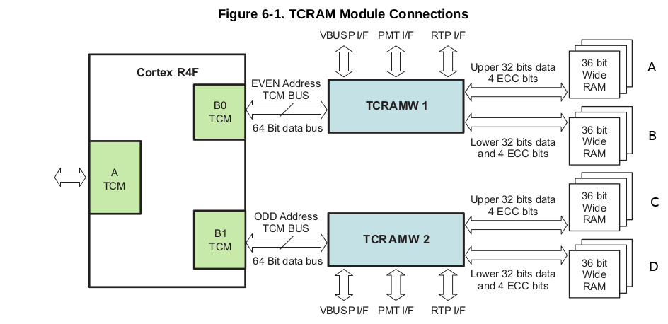
The following picture from the RM48x technical reference manual (SPNU503B – November 2012 – Revised August 2013 p 297) raises some questions.
Here is what I know and understand:
- Only one of the two Cortex R4F's is drawn, the second one also has its own B0TCM and B1TCM.
- From the ARM Cortex-R4F technical reference manual I found that a single R4F is allowed to have two BTCM interfaces, these BTCM interfaces are interleaved on either
- Bit[3] of the address
- On the MSB
- The RM48L952 has two RAM bank
Now the following sentence of the RM48L952 datasheet ( SPNS177D – SEPTEMBER 2011 – REVISED JUNE 2015 p 85) confuses me.
Features of the TCRAM :
"Provides enhanced safety for the RAM addressing by implementing two 36-bit-wide byte-interleaved RAM banks
and generating independent RAM access control signals to the two banks"
On the picture however i see 4 36-bit wide RAMS (I labeled them A, B, C, D).
I do not understand the relation between this picture and sentence I quoted.
A couple of concrete questions:
1) How many RAM banks are there?
2) How are A, B, C and D fit into these banks?
3) If I declare a uint8_t array[16] = {0x00, 0x11, 0x22, 0x33, 0x44 .. 0xFF};
How is this stored into / divided over the memory banks (or regions? ABCD)?
Thanks in advance,
Best regards.
Karel