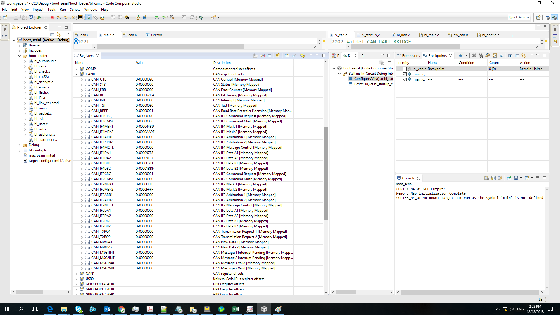
Tool/software: Code Composer Studio
I am using EK-TM4C1294XL Kit to built an application and i success to built this application but, now i need to flash my kit over can bus so i decided to use Ti bootloader according to TivaWare™ Boot Loader Document i update Serial boot example located at "ti\TivaWare_C_Series-2.1.4.178\examples\boards\ek-tm4c1294xl\boot_serial" to use CAN bus 0 instead of UART but i can't transmit or receive any data over this bus . below show the updates which i apply on bl_config.h file
//*****************************************************************************
#define CAN_ENABLE_UPDATE
//*****************************************************************************
//
// The GPIO module to enable in order to configure the CAN0 Rx pin. This will
// be one of the SYSCTL_RCGC2_GPIOx values, where "x" is replaced with the port
// name (such as B). The value of "x" should match the value of "x" for
// CAN_RX_PORT.
//
// Depends on: CAN_ENABLE_UPDATE
// Exclusive of: None
// Requires: None
//
//*****************************************************************************
#define CAN_RX_PERIPH SYSCTL_RCGC2_GPIOA
//*****************************************************************************
//
// The GPIO port used to configure the CAN0 Rx pin. This will be one of the
// GPIO_PORTx_BASE values, where "x" is replaced with the port name (such as
// B). The value of "x" should match the value of "x" for CAN_RX_PERIPH.
//
// Depends on: CAN_ENABLE_UPDATE
// Exclusive of: None
// Requires: None
//
//*****************************************************************************
#define CAN_RX_PORT GPIO_PORTA_BASE
//*****************************************************************************
//
// The GPIO pin that is shared with the CAN0 Rx pin. This is a value between 0
// and 7.
//
// Depends on: CAN_ENABLE_UPDATE
// Exclusive of: None
// Requires: None
//
//*****************************************************************************
#define CAN_RX_PIN 0
#define CAN_RX_PIN_PCTL 7
//*****************************************************************************
//
// The GPIO module to enable in order to configure the CAN0 Tx pin. This will
// be one of the SYSCTL_RCGC2_GPIOx values, where "x" is replaced with the port
// name (such as B). The value of "x" should match the value of "x" for
// CAN_TX_PORT.
//
// Depends on: CAN_ENABLE_UPDATE
// Exclusive of: None
// Requires: None
//
//*****************************************************************************
#define CAN_TX_PERIPH SYSCTL_RCGC2_GPIOA
//*****************************************************************************
//
// The GPIO port used to configure the CAN0 Tx pin. This will be one of the
// GPIO_PORTx_BASE values, where "x" is replaced with the port name (such as
// B). The value of "x" should match the value of "x" for CAN_TX_PERIPH.
//
// Depends on: CAN_ENABLE_UPDATE
// Exclusive of: None
// Requires: None
//
//*****************************************************************************
#define CAN_TX_PORT GPIO_PORTA_BASE
//*****************************************************************************
//
// The GPIO pin that is shared with the CAN0 Tx pin. This is a value between 0
// and 7.
//
// Depends on: CAN_ENABLE_UPDATE
// Exclusive of: None
// Requires: None
//
//*****************************************************************************
#define CAN_TX_PIN 1
#define CAN_TX_PIN_PCTL 7
//*****************************************************************************
//
// The bit rate used on the CAN bus. This must be one of 20000, 50000, 125000,
// 250000, 500000, or 1000000. The CAN bit rate must be less than or equal to
// the crystal frequency divided by 8 (CRYSTAL_FREQ / 8).
//
// Depends on: CAN_ENABLE_UPDATE
// Exclusive of: None
// Requires: None
//
//*****************************************************************************
#define CAN_BIT_RATE 20000


