This thread has been locked.

If you have a related question, please click the "Ask a related question" button in the top right corner. The newly created question will be automatically linked to this question.

TM4C1231E6PM: High output level aleatory drop

Part Number: TM4C1231E6PM

Dear Sirs

The PB6 of TM4C1231E6PM is configured as output. The pin is driving mosfet BSS138 that tuns on/off a relay.

ROM_SysCtlPeripheralEnable(SYSCTL_PERIPH_GPIOB);
ROM_GPIOPinTypeGPIOOutput(GPIO_PORTB_BASE,GPIO_PIN_6 );

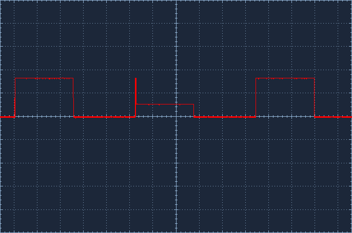
The output has an aleatory behavior. Most of the times the High Output is, as expected, 3.3V. But sometimes it's 1.1V which cause the relay to remain off.

I checked the supply behavior with a scope and is consistently  3.3V.

I have been try to find the bug for some days.

Regards

Ysaac

  • Do you have a current limiting resistor (say 1K) in series between PB6 and the gate of the mosfet? That will make it clear if the issue is in the output of the micro, or the mosfet.
  • Dear Bob

    I really dont have any gate current limiting resistor. I will include one and let you know.

    But why do i need to include one, if inherently the input resistance of a mosfet is high?

    Regards

    Ysaac

  • Dear Bob
    I added a limiter resistor. The problem still persist but seems to be less frequently.
    Any Help?
    Regards
    Ysaac
  • When the problem occurs, what is the voltage on each side of the current limiting resistor? If the voltage is the same on both sides (1.1V) can you connect to the device with Code Composer Studio and display the GPIOB registers? Verify that GPIO_DIR still shows pin PB6 as an output.
  • Dear Bob

    The voltage is 1.06V an 0.96V  ( i.e. 0.1V voltage drop) in each side if the limiting resistor.

    I noted that the problem doesn't occur when the relay is no load in the contacts.

    I verified the GPIO_DIR and the pin still shows as output.

    This is the fault as seen in the scope.

    Regards

    Ysaac

  • It looks like some of the ESD protection circuit on PB6 is being activated. You might zoom in your scope on the rising edge of the failing condition. (Getting a proper scope ground is critical.) Is a kickback from the load switch causing the pin to momentarily drop below ground or above Vdd? Is it causing a particularly fast rise time (< 2nS)?
  • Dear Bob

    You are right. This is  EMI interference from the relay switching.

    I tried a lot of things: Tvs Diodes, Movs, etc

    The only way I found to solve the problem was to sync the relay switching with the AC mains. I added a zero cross detector to sync the signal to the AC mains.

    Do you have any other idea?

    Regards

    Ysaac

  • I thought the problem was solved. It seems to work because the zero cross detector synchronize the signal when it is sill high. But it doesn't solve the problem.

    What do you think?

    I have invested a lot of time guessing what is the problem.

    Regards

    Ysaac

  • The remedies you listed above, diodes ... etc., are primarily for snubbing conducted emissions. You might want to evaluate your system for radiated emissions. Both from the standpoint of the high current emission sources and the susceptibility of the traces connected to the microcontroller. Minimize the loop area of circuit paths with twisted wire cabling. Does the board with the microcontroller have a ground plane?
  • The power PCB is separate from the microcontroller,and yes, there is a ground plane.

    I have been making some testing, I added a optoisolator between the micro and the mosfet and it seem to work so far. 
    Regards
    Ysaac
  • I did more research. I isolated completely the relay from the micro using a 3.3 battery to supply the optocoupler output. The problem was reduced but not eliminated.
    The second step was to eliminate the ac mains that was connected to the contactor. I observed that even turning on (not off) affect the micro what obviously is related to EMI.
    Any suggestion?
  • I mean turning on (not off) the the office light affect the micro
  • This does look like susceptibility to radiated emissions. Do you have wires that connect to the micro and go off board? If so, replace them with twisted pairs, the other wire grounded.
  • I replaced the cable with twisted pair an doesn't solve the problem.

    I put a 100n capacitor between the gpio pin and GND and is working so far. I don't know exactly why it works but it seems that capacitor adds kind of transient suppressor.


  • Part of the ESD protection on the I/O pins reacts to fast rise times. It is possible that the RC created by the capacitor reduced the rise time of the induced noise so that the protection circuit is no longer firing. If it continues to work well, you have a solution.