This thread has been locked.

If you have a related question, please click the "Ask a related question" button in the top right corner. The newly created question will be automatically linked to this question.

CCS/EK-TM4C123GXL: Unable to receive data using SSI(SSI_FRF_MOTO_MODE_0) as slave

Part Number: EK-TM4C123GXL

Tool/software: Code Composer Studio

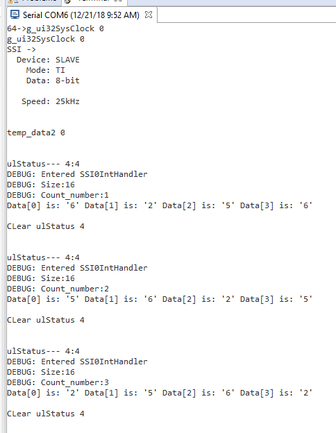
Hi, I am trying to use my EK-TM4C123GXL launch pad as a SSI/SPI slave device. I have tried some sample code based on an online resource which is using SSI0 Interrupts. When I tried sending data from my master (a Linux based platform) device to the launchpad, the SSI0IntHandler is not triggered and I am not seeing any received data.

I wonder if my code using interrupts to receive data is correct. Or there is a much simpler way to view the received data (I dont mind using the polling method) with sample code.

Note: My master is working fine as I am able to receive the data from it without any issues using an aardvark device as a slave. I have commented out  sendTxSSI() in my code.

#include <stdbool.h>
#include <stdint.h>
#include "inc/hw_ints.h"
#include "inc/hw_memmap.h"
#include "inc/hw_nvic.h"
#include "driverlib/gpio.h"
#include "driverlib/pin_map.h"
#include "driverlib/ssi.h"
#include "driverlib/sysctl.h"
#include "driverlib/uart.h"
#include "utils/uartstdio.h"
#include "driverlib/timer.h"

//*****************************************************************************
//
//! \addtogroup ssi_examples_list
//! <h1>TI Master (ti_master)</h1>
//!
//! This example shows how to configure the SSI0 as TI Master.  The code will
//! send three characters on the master Tx then poll the receive FIFO until
//! 3 characters are received on the master Rx.
//!
//! This example uses the following peripherals and I/O signals.  You must
//! review these and change as needed for your own board:
//! - SSI0 peripheral
//! - GPIO Port A peripheral (for SSI0 pins)
//! - SSI0Clk - PA2
//! - SSI0Fss - PA3
//! - SSI0Rx  - PA4
//! - SSI0Tx  - PA5
//!
//! The following UART signals are configured only for displaying console
//! messages for this example.  These are not required for operation of I2C0.
//! - UART0 peripheral
//! - GPIO Port A peripheral (for UART0 pins)
//! - UART0RX - PA0
//! - UART0TX - PA1
//!
//! This example uses the following interrupt handlers.  To use this example
//! in your own application you must add these interrupt handlers to your
//! vector table.
//! - None.
//
//*****************************************************************************

//*****************************************************************************
//
// Number of bytes to send and receive.
//
//*****************************************************************************
#define NUM_SSI_DATA            3

uint32_t g_ui32SysClock;
uint32_t g_ulDataRx1[4],g_ulDataRx2;
uint8_t  g_ulSSI2RXTO;
uint8_t flag =0;
uint8_t temp_data = 0;
uint32_t Count = 0;
uint8_t Send_flag = 0;
volatile uint32_t millis = 0;
uint32_t g_uc_timer = 0;
uint32_t ulStatus = 0;

/*
  Interrupt handler for the timer
*/
void SysTickInt(void)
{
  uint32_t status=0;

  status = TimerIntStatus(TIMER5_BASE,true);
  TimerIntClear(TIMER5_BASE,status);
  millis++;
}
void
SSI0IntHandler(void)
{
	//
	// Read interrupt status.
	//
	ulStatus = SSIIntStatus(SSI0_BASE, 1);

	//
	// Check the reason for the interrupt.
	//
//	if(ulStatus & SSI_RXFF)
	UARTprintf("\n\nulStatus--- %x:%x\n",ulStatus,ulStatus & SSI_RXFF);
//	if(ulStatus & SSI_RXTO)
	if(ulStatus & SSI_RXFF)
	{
		//
		// Interrupt is because of RX time out.  So increment counter to tell
		// main loop that RX timeout interrupt occurred.
		//


		//
		// Read NUM_SSI_DATA bytes of data from SSI2 RX FIFO.
		//
	//	SSIDataGet(SSI0_BASE, &g_ulDataRx1[0]);
	//	SSIDataPut(SSI0_BASE, 0x1111);//Dummy Write
		//sendTxSSI();
	while(!SSIDataGetNonBlocking(SSI0_BASE, &g_ulDataRx1[0]))
	{
	}
	while(!SSIDataGetNonBlocking(SSI0_BASE, &g_ulDataRx1[1]))
	{
	}
	while(!SSIDataGetNonBlocking(SSI0_BASE, &g_ulDataRx1[2]))
	{
	}
	while(!SSIDataGetNonBlocking(SSI0_BASE, &g_ulDataRx1[3]))
	{
	}
	g_ulSSI2RXTO = 1;
		//temp_data-=2;
		//SSIDataGet(SSI0_BASE, &g_ulDataRx2);
	}

	//
	// Clear interrupts.
	//
	UARTprintf("\n\nCLear ulStatus %x\n",ulStatus);
	SSIIntClear(SSI0_BASE, ulStatus);
	//SSIIntClear(SSI0_BASE, SSI_RXFF);
}
//*****************************************************************************
//
// This function sets up UART0 to be used for a console to display information
// as the example is running.
//
//*****************************************************************************
void
InitConsole(void)
{
    //
    // Enable GPIO port A which is used for UART0 pins.
    // TODO: change this to whichever GPIO port you are using.
    //
    SysCtlPeripheralEnable(SYSCTL_PERIPH_GPIOA);

    //
    // Configure the pin muxing for UART0 functions on port A0 and A1.
    // This step is not necessary if your part does not support pin muxing.
    // TODO: change this to select the port/pin you are using.
    //
    GPIOPinConfigure(GPIO_PA0_U0RX);
    GPIOPinConfigure(GPIO_PA1_U0TX);

    //
    // Enable UART0 so that we can configure the clock.
    //
    SysCtlPeripheralEnable(SYSCTL_PERIPH_UART0);

    //
    // Use the internal 16MHz oscillator as the UART clock source.
    //
    UARTClockSourceSet(UART0_BASE, UART_CLOCK_PIOSC);

    //
    // Select the alternate (UART) function for these pins.
    // TODO: change this to select the port/pin you are using.
    //
    GPIOPinTypeUART(GPIO_PORTA_BASE, GPIO_PIN_0 | GPIO_PIN_1);

    //
    // Initialize the UART for console I/O.
    //
    UARTStdioConfig(0, 115200, 16000000);
}


/*
  Timer setup
*/
void TimerBegin(){

  //We set the load value so the timer interrupts each 1ms
  uint32_t Period;
// Period = 80000; //1ms
//  Period = 833;//10us
//  Period = 100;//2.5us
  Period = 1190;//us

  SysCtlPeripheralEnable(SYSCTL_PERIPH_TIMER5);
  SysCtlDelay(3);
  /*
    Configure the timer as periodic, by omission it's in count down mode.
    It counts from the load value to 0 and then resets back to the load value.
  REMEMBER: You need to configure the timer before setting the load and match
  */
  TimerConfigure(TIMER5_BASE, TIMER_CFG_PERIODIC);
  TimerLoadSet(TIMER5_BASE, TIMER_A, Period -1);


  TimerIntRegister(TIMER5_BASE, TIMER_A, SysTickInt);

  /*
    Enable the timeout interrupt. In count down mode it's when the timer reaches
  0 and resets back to load. In count up mode it's when the timer reaches load
  and resets back to 0.
  */
  TimerIntEnable(TIMER5_BASE, TIMER_TIMA_TIMEOUT);

  TimerEnable(TIMER5_BASE, TIMER_A);
}

/*
  This is the delay function.
*/
void Wait (uint32_t tempo) {
  volatile uint32_t temp = millis;
  while ( (millis-temp) < tempo);
}


void sendTxSSI()
{
    uint32_t ulDataTx;
    uint32_t ulDataRx;
    uint32_t ulDataTx1 =0;

	ulDataTx = 0x8001;
	ulDataTx1 = 0x7FFC;

	    	//if(flag == 0)
	    	//{
	if (SSIDataPutNonBlocking(SSI0_BASE,0x1111) != 0 ) // puts a data at SSI transmit FIFO
	{
	  UARTprintf("\nTX:%x\n\r", ulDataTx);
	}

	if (SSIDataPutNonBlocking(SSI0_BASE,ulDataTx) != 0 )
	{
	  UARTprintf("\nTX:%x\n\r", ulDataTx);
	}
	               //Wait until SSI0 is done transferring all the data in the transmit FIFO.
//	                while( SSIBusy(SSI0_BASE) )
//	                  { ; }

	    //	}
	 ulDataTx++;
	 if ( SSIDataPutNonBlocking(SSI0_BASE, ulDataTx) != 0 )
	 {
	     UARTprintf("TX:%x\n\r", ulDataTx);
	 }

//	        while( SSIBusy(SSI0_BASE) )
//	                      { ; }

	        //	}
	  if ( SSIDataPutNonBlocking(SSI0_BASE, ulDataTx1) != 0 )
	  {
	      UARTprintf("TX:%x\n\r", ulDataTx1);
	  }

//	            while( SSIBusy(SSI0_BASE) )
//	                          { ; }

	            //	}
	   ulDataTx1++;
	   if ( SSIDataPutNonBlocking(SSI0_BASE, ulDataTx1) != 0 )
	   {
	      UARTprintf("TX:%x\n\r", ulDataTx1);
	      temp_data ++;
	      UARTprintf("\ntemp_data1 %d\n",temp_data);
	   }
//	                while( SSIBusy(SSI0_BASE) )
//	                  { ; }
}
//*****************************************************************************
//
// Configure SSI0 in master TI mode.  This example will send out 3 bytes of
// data, then wait for 3 bytes of data to come in.  This will all be done using
// the polling method.
//
//*****************************************************************************
int
main(void)
{
    //
    // Set the clocking to run directly from the external crystal/oscillator.
    // TODO: The SYSCTL_XTAL_ value must be changed to match the value of the
    // crystal on your board.
    //

    g_ui32SysClock = SysCtlClockFreqSet((SYSCTL_OSC_INT | SYSCTL_USE_PLL | SYSCTL_CFG_VCO_480),120000000);

    //
    // Set up the serial console to use for displaying messages.  This is
    // just for this example program and is not needed for SSI operation.
    //
    InitConsole();
    UARTprintf("64->g_ui32SysClock %d\n",g_ui32SysClock);


       UARTprintf("g_ui32SysClock %d\n",g_ui32SysClock);
    //
    // Display the setup on the console.
    //
    UARTprintf("SSI ->\n");
    UARTprintf("  Device: SLAVE\n");
    UARTprintf("    Mode: TI\n");
    UARTprintf("    Data: 8-bit\n\n");
    UARTprintf("   Speed: 25kHz\n\n");


    	TimerBegin();

      SysCtlPeripheralEnable(SYSCTL_PERIPH_GPIOF);
      SysCtlDelay(3);

      //Set the pin of your choise to output
      GPIOPinTypeGPIOOutput(GPIO_PORTF_BASE, GPIO_PIN_1);
    //
    // The SSI0 peripheral must be enabled for use.
    //
    SysCtlPeripheralEnable(SYSCTL_PERIPH_SSI0);

    //
    // For this example SSI0 is used with PortA[5:2].  The actual port and
    // pins used may be different on your part, consult the data sheet for
    // more information.  GPIO port A needs to be enabled so these pins can
    // be used.
    // TODO: change this to whichever GPIO port you are using.
    //
    SysCtlPeripheralEnable(SYSCTL_PERIPH_GPIOA);

    //
    // Configure the pin muxing for SSI0 functions on port A2, A3, A4, and A5.
    // This step is not necessary if your part does not support pin muxing.
    // TODO: change this to select the port/pin you are using.
    //
    GPIOPinConfigure(GPIO_PA2_SSI0CLK);
    GPIOPinConfigure(GPIO_PA3_SSI0FSS);
    GPIOPinConfigure(GPIO_PA4_SSI0RX);
    GPIOPinConfigure(GPIO_PA5_SSI0TX);

    //
    // Configure the GPIO settings for the SSI pins.  This function also gives
    // control of these pins to the SSI hardware.  Consult the data sheet to
    // see which functions are allocated per pin.
    // The pins are assigned as follows:
    //      PA5 - SSI0Tx
    //      PA4 - SSI0Rx
    //      PA3 - SSI0Fss
    //      PA2 - SSI0CLK
    // TODO: change this to select the port/pin you are using.
    //
    GPIOPinTypeSSI(GPIO_PORTA_BASE, GPIO_PIN_5 | GPIO_PIN_4 | GPIO_PIN_3 |
                   GPIO_PIN_2);

    //
    // Configure and enable the SSI port for SPI master mode.  Use SSI0,
    // system clock supply, idle clock level low and active low clock in
    // freescale SPI mode, master mode, 1MHz SSI frequency, and 8-bit data.
    // For SPI mode, you can set the polarity of the SSI clock when the SSI
    // unit is idle.  You can also configure what clock edge you want to
    // capture data on.  Please reference the datasheet for more information on
    // the different SPI modes.
    //
#if defined(TARGET_IS_TM4C129_RA0) ||                                         \
    defined(TARGET_IS_TM4C129_RA1) ||                                         \
    defined(TARGET_IS_TM4C129_RA2)
    SSIConfigSetExpClk(SSI0_BASE, ui32SysClock, SSI_FRF_MOTO_MODE_0,
                       SSI_MODE_SLAVE, 25000, 8);
#else
    SSIConfigSetExpClk(SSI0_BASE, SysCtlClockGet(), SSI_FRF_MOTO_MODE_0,
                       SSI_MODE_SLAVE, 25000, 8);
#endif

    //
    // Enable the SSI0 module.
    //
    SSIEnable(SSI0_BASE);

    SSIIntEnable(SSI0_BASE, SSI_RXFF);
       // SSIIntDisable(SSI0_BASE, SSI_TXFF);
    	SSIIntDisable(SSI0_BASE, SSI_TXEOT);
    	SSIIntDisable(SSI0_BASE, SSI_RXTO);
    	SSIIntDisable(SSI0_BASE, SSI_RXOR);

    SSIIntClear(SSI0_BASE, SSI_RXFF);
   // SSIIntClear(SSI0_BASE, SSI_TXFF);
    // SSIIntClear(SSI0_BASE, SSI_RXTO);
    //SSIIntClear(SSI0_BASE, SSI_RXOR);

    //
    // Read any residual data from the SSI port.  This makes sure the receive
    // FIFOs are empty, so we don't read any unwanted junk.  This is done here
    // because the TI SSI mode is full-duplex, which allows you to send and
    // receive at the same time.  The SSIDataGetNonBlocking function returns
    // "true" when data was returned, and "false" when no data was returned.
    // The "non-blocking" function checks if there is any data in the receive
    // FIFO and does not "hang" if there isn't.
    //
    while(SSIDataGetNonBlocking(SSI0_BASE, &g_ulDataRx1[0]))
    {
    }

    //
    // Initialize the data to send.
    //
    IntEnable(INT_SSI0);
    g_uc_timer = millis;
    UARTprintf("\ntemp_data2 %d\n",temp_data);
    while(1){
    	//UARTprintf("\n1.temp_data %d\n",temp_data);
    	if(g_ulSSI2RXTO != 0){
			UARTprintf("\ng_ulSSI2RXTO %d Count %d\n",g_ulSSI2RXTO,Count);
			g_ulSSI2RXTO = 0;
			Count++;
			UARTprintf("\nRX.%x\n\r", g_ulDataRx1[0]);
			UARTprintf("RX.%x\n\r", g_ulDataRx1[1]);
			UARTprintf("RX.%x\n\r", g_ulDataRx1[2]);
			UARTprintf("RX.%x\n\r", g_ulDataRx1[3]);
			//UARTprintf("\nSEND DATA BACK TO MASTER\n");
			//sendTxSSI();
		}
    }


    return(0);
}

  • Hello Gowtham,

    You are missing the SSIIntRegister API to associate your ISR handler with the SSI0 interrupt:

    SSIIntRegister(SSI0_BASE, SSI0IntHandler);

  • Hi Ralph,

    Thank you for the feedback. With SSIIntRegister(SSI0_BASE, SSI0IntHandler), I am able to receive data inside SSI0IntHandler. However, the received data is not accurate. When I transmit (Hex Data: 10,11,12,13) from the master, my receive data are either ( Dec Data: {6, 2, 5, 6} or {5,6,2,5} or {2,5,6,2} ). At times, only 2 or 3 data are received instead of all 4 data.

    I did some modification to the original code. Attached the modified code "receive_working_but_wrong_data.c" and the terminal output.

    //*****************************************************************************
    //
    // ti_master.c - Example demonstrating how to configure SSI0 in TI master mode.
    //
    // Copyright (c) 2010-2014 Texas Instruments Incorporated.  All rights reserved.
    // Software License Agreement
    //
    //   Redistribution and use in source and binary forms, with or without
    //   modification, are permitted provided that the following conditions
    //   are met:
    //
    //   Redistributions of source code must retain the above copyright
    //   notice, this list of conditions and the following disclaimer.
    //
    //   Redistributions in binary form must reproduce the above copyright
    //   notice, this list of conditions and the following disclaimer in the
    //   documentation and/or other materials provided with the
    //   distribution.
    //
    //   Neither the name of Texas Instruments Incorporated nor the names of
    //   its contributors may be used to endorse or promote products derived
    //   from this software without specific prior written permission.
    //
    // THIS SOFTWARE IS PROVIDED BY THE COPYRIGHT HOLDERS AND CONTRIBUTORS
    // "AS IS" AND ANY EXPRESS OR IMPLIED WARRANTIES, INCLUDING, BUT NOT
    // LIMITED TO, THE IMPLIED WARRANTIES OF MERCHANTABILITY AND FITNESS FOR
    // A PARTICULAR PURPOSE ARE DISCLAIMED. IN NO EVENT SHALL THE COPYRIGHT
    // OWNER OR CONTRIBUTORS BE LIABLE FOR ANY DIRECT, INDIRECT, INCIDENTAL,
    // SPECIAL, EXEMPLARY, OR CONSEQUENTIAL DAMAGES (INCLUDING, BUT NOT
    // LIMITED TO, PROCUREMENT OF SUBSTITUTE GOODS OR SERVICES; LOSS OF USE,
    // DATA, OR PROFITS; OR BUSINESS INTERRUPTION) HOWEVER CAUSED AND ON ANY
    // THEORY OF LIABILITY, WHETHER IN CONTRACT, STRICT LIABILITY, OR TORT
    // (INCLUDING NEGLIGENCE OR OTHERWISE) ARISING IN ANY WAY OUT OF THE USE
    // OF THIS SOFTWARE, EVEN IF ADVISED OF THE POSSIBILITY OF SUCH DAMAGE.
    //
    // This is part of revision 2.1.0.12573 of the Tiva Firmware Development Package.
    //
    //*****************************************************************************
    
    #include <stdbool.h>
    #include <stdint.h>
    #include "inc/hw_ints.h"
    #include "inc/hw_memmap.h"
    #include "inc/hw_nvic.h"
    #include "driverlib/gpio.h"
    #include "driverlib/pin_map.h"
    #include "driverlib/ssi.h"
    #include "driverlib/sysctl.h"
    #include "driverlib/uart.h"
    #include "utils/uartstdio.h"
    #include "driverlib/timer.h"
    
    //*****************************************************************************
    //
    //! \addtogroup ssi_examples_list
    //! <h1>TI Master (ti_master)</h1>
    //!
    //! This example shows how to configure the SSI0 as TI Master.  The code will
    //! send three characters on the master Tx then poll the receive FIFO until
    //! 3 characters are received on the master Rx.
    //!
    //! This example uses the following peripherals and I/O signals.  You must
    //! review these and change as needed for your own board:
    //! - SSI0 peripheral
    //! - GPIO Port A peripheral (for SSI0 pins)
    //! - SSI0Clk - PA2
    //! - SSI0Fss - PA3
    //! - SSI0Rx  - PA4
    //! - SSI0Tx  - PA5
    //!
    //! The following UART signals are configured only for displaying console
    //! messages for this example.  These are not required for operation of I2C0.
    //! - UART0 peripheral
    //! - GPIO Port A peripheral (for UART0 pins)
    //! - UART0RX - PA0
    //! - UART0TX - PA1
    //!
    //! This example uses the following interrupt handlers.  To use this example
    //! in your own application you must add these interrupt handlers to your
    //! vector table.
    //! - None.
    //
    //*****************************************************************************
    
    //*****************************************************************************
    //
    // Number of bytes to send and receive.
    //
    //*****************************************************************************
    #define NUM_SSI_DATA            3
    
    uint32_t g_ui32SysClock;
    uint32_t g_ulDataRx1[4],g_ulDataRx2;
    uint8_t  g_ulSSI2RXTO;
    uint8_t flag =0;
    uint8_t temp_data = 0;
    uint32_t Count = 0;
    uint8_t Send_flag = 0;
    volatile uint32_t millis = 0;
    uint32_t g_uc_timer = 0;
    uint32_t ulStatus = 0;
    uint32_t ui32Index = 0;
    
    /*
      Interrupt handler for the timer
    */
    void SysTickInt(void)
    {
      uint32_t status=0;
    
      status = TimerIntStatus(TIMER5_BASE,true);
      TimerIntClear(TIMER5_BASE,status);
      millis++;
    }
    void
    SSI0IntHandler(void)
    {
    	//
    	// Read interrupt status.
    	//
    	ulStatus = SSIIntStatus(SSI0_BASE, 1);
    
    	//
    	// Check the reason for the interrupt.
    	//
    //	if(ulStatus & SSI_RXFF)
    	UARTprintf("\n\nulStatus--- %x:%x\n",ulStatus,ulStatus & SSI_RXFF);
    //	if(ulStatus & SSI_RXTO)
    	if(ulStatus & SSI_RXFF)
    	{
    		Count = Count + 1;
    		//
    		// Interrupt is because of RX time out.  So increment counter to tell
    		// main loop that RX timeout interrupt occurred.
    		//
    
    
    		//
    		// Read NUM_SSI_DATA bytes of data from SSI2 RX FIFO.
    		//
    		//SSIDataGet(SSI0_BASE, &g_ulDataRx1[0]);
    		//SSIDataPut(SSI0_BASE, 0x1111);//Dummy Write
    		//sendTxSSI();
    		UARTprintf("DEBUG: Entered SSI0IntHandler\n");
    		UARTprintf("DEBUG: Size:%d\n",sizeof g_ulDataRx1);
    		while(!SSIDataGetNonBlocking(SSI0_BASE, &g_ulDataRx1[0]));
    		UARTprintf("DEBUG: Count_number:%d\n",Count);
    		for(ui32Index = 0; ui32Index < 4; ui32Index++){
    		   //
    		   // Receive the data using the "blocking" Get function. This function
    		   // will wait until there is data in the receive FIFO before returning.
    		   //
    		   SSIDataGet(SSI0_BASE, &g_ulDataRx1[ui32Index]);
    		   //
    		   // Since we are using 8-bit data, mask off the MSB.
    		   //
    		   g_ulDataRx1[ui32Index] &= 0x00FF;
    		   //
    		   // Display the data that SSI0 received.
    		   //
    		   UARTprintf("Data[%d] is: '%d' ",ui32Index , g_ulDataRx1[ui32Index]);
    		}
    
    		g_ulSSI2RXTO = 1;
    		//temp_data-=2;
    		//SSIDataGet(SSI0_BASE, &g_ulDataRx2);
    	}
    
    	//
    	// Clear interrupts.
    	//
    	UARTprintf("\n\nCLear ulStatus %x\n",ulStatus);
    	SSIIntClear(SSI0_BASE, ulStatus);
    	//SSIIntClear(SSI0_BASE, SSI_RXFF);
    }
    //*****************************************************************************
    //
    // This function sets up UART0 to be used for a console to display information
    // as the example is running.
    //
    //*****************************************************************************
    void
    InitConsole(void)
    {
        //
        // Enable GPIO port A which is used for UART0 pins.
        // TODO: change this to whichever GPIO port you are using.
        //
        SysCtlPeripheralEnable(SYSCTL_PERIPH_GPIOA);
    
        //
        // Configure the pin muxing for UART0 functions on port A0 and A1.
        // This step is not necessary if your part does not support pin muxing.
        // TODO: change this to select the port/pin you are using.
        //
        GPIOPinConfigure(GPIO_PA0_U0RX);
        GPIOPinConfigure(GPIO_PA1_U0TX);
    
        //
        // Enable UART0 so that we can configure the clock.
        //
        SysCtlPeripheralEnable(SYSCTL_PERIPH_UART0);
    
        //
        // Use the internal 16MHz oscillator as the UART clock source.
        //
        UARTClockSourceSet(UART0_BASE, UART_CLOCK_PIOSC);
    
        //
        // Select the alternate (UART) function for these pins.
        // TODO: change this to select the port/pin you are using.
        //
        GPIOPinTypeUART(GPIO_PORTA_BASE, GPIO_PIN_0 | GPIO_PIN_1);
    
        //
        // Initialize the UART for console I/O.
        //
        UARTStdioConfig(0, 115200, 16000000);
    }
    
    
    /*
      Timer setup
    */
    void TimerBegin(){
    
      //We set the load value so the timer interrupts each 1ms
      uint32_t Period;
    // Period = 80000; //1ms
    //  Period = 833;//10us
    //  Period = 100;//2.5us
      Period = 1190;//us
    
      SysCtlPeripheralEnable(SYSCTL_PERIPH_TIMER5);
      SysCtlDelay(3);
      /*
        Configure the timer as periodic, by omission it's in count down mode.
        It counts from the load value to 0 and then resets back to the load value.
      REMEMBER: You need to configure the timer before setting the load and match
      */
      TimerConfigure(TIMER5_BASE, TIMER_CFG_PERIODIC);
      TimerLoadSet(TIMER5_BASE, TIMER_A, Period -1);
    
    
      TimerIntRegister(TIMER5_BASE, TIMER_A, SysTickInt);
    
      /*
        Enable the timeout interrupt. In count down mode it's when the timer reaches
      0 and resets back to load. In count up mode it's when the timer reaches load
      and resets back to 0.
      */
      TimerIntEnable(TIMER5_BASE, TIMER_TIMA_TIMEOUT);
    
      TimerEnable(TIMER5_BASE, TIMER_A);
    }
    
    /*
      This is the delay function.
    */
    void Wait (uint32_t tempo) {
      volatile uint32_t temp = millis;
      while ( (millis-temp) < tempo);
    }
    
    
    void sendTxSSI()
    {
        uint32_t ulDataTx;
        uint32_t ulDataRx;
        uint32_t ulDataTx1 =0;
    
    	ulDataTx = 0x8001;
    	ulDataTx1 = 0x7FFC;
    
    	    	//if(flag == 0)
    	    	//{
    	if (SSIDataPutNonBlocking(SSI0_BASE,0x1111) != 0 ) // puts a data at SSI transmit FIFO
    	{
    	  UARTprintf("\nTX:%x\n\r", ulDataTx);
    	}
    
    	if (SSIDataPutNonBlocking(SSI0_BASE,ulDataTx) != 0 )
    	{
    	  UARTprintf("\nTX:%x\n\r", ulDataTx);
    	}
    	               //Wait until SSI0 is done transferring all the data in the transmit FIFO.
    //	                while( SSIBusy(SSI0_BASE) )
    //	                  { ; }
    
    	    //	}
    	 ulDataTx++;
    	 if ( SSIDataPutNonBlocking(SSI0_BASE, ulDataTx) != 0 )
    	 {
    	     UARTprintf("TX:%x\n\r", ulDataTx);
    	 }
    
    //	        while( SSIBusy(SSI0_BASE) )
    //	                      { ; }
    
    	        //	}
    	  if ( SSIDataPutNonBlocking(SSI0_BASE, ulDataTx1) != 0 )
    	  {
    	      UARTprintf("TX:%x\n\r", ulDataTx1);
    	  }
    
    //	            while( SSIBusy(SSI0_BASE) )
    //	                          { ; }
    
    	            //	}
    	   ulDataTx1++;
    	   if ( SSIDataPutNonBlocking(SSI0_BASE, ulDataTx1) != 0 )
    	   {
    	      UARTprintf("TX:%x\n\r", ulDataTx1);
    	      temp_data ++;
    	      UARTprintf("\ntemp_data1 %d\n",temp_data);
    	   }
    //	                while( SSIBusy(SSI0_BASE) )
    //	                  { ; }
    }
    //*****************************************************************************
    //
    // Configure SSI0 in master TI mode.  This example will send out 3 bytes of
    // data, then wait for 3 bytes of data to come in.  This will all be done using
    // the polling method.
    //
    //*****************************************************************************
    int
    main(void)
    {
        //
        // Set the clocking to run directly from the external crystal/oscillator.
        // TODO: The SYSCTL_XTAL_ value must be changed to match the value of the
        // crystal on your board.
        //
    
        g_ui32SysClock = SysCtlClockFreqSet((SYSCTL_OSC_INT | SYSCTL_USE_PLL | SYSCTL_CFG_VCO_480),120000000);
    
        //
        // Set up the serial console to use for displaying messages.  This is
        // just for this example program and is not needed for SSI operation.
        //
        InitConsole();
        UARTprintf("64->g_ui32SysClock %d\n",g_ui32SysClock);


        UARTprintf("g_ui32SysClock %d\n",g_ui32SysClock);
        //
        // Display the setup on the console.
        //
        UARTprintf("SSI ->\n");
        UARTprintf("  Device: SLAVE\n");
        UARTprintf("    Mode: TI\n");
        UARTprintf("    Data: 8-bit\n\n");
        UARTprintf("   Speed: 25kHz\n\n");
    
    
        TimerBegin();
    
         SysCtlPeripheralEnable(SYSCTL_PERIPH_GPIOF);
         SysCtlDelay(3);
    
         //Set the pin of your choise to output
         GPIOPinTypeGPIOOutput(GPIO_PORTF_BASE, GPIO_PIN_1);
        //
        // The SSI0 peripheral must be enabled for use.
        //
        SysCtlPeripheralEnable(SYSCTL_PERIPH_SSI0);
    
        //
        // For this example SSI0 is used with PortA[5:2].  The actual port and
        // pins used may be different on your part, consult the data sheet for
        // more information.  GPIO port A needs to be enabled so these pins can
        // be used.
        // TODO: change this to whichever GPIO port you are using.
        //
        SysCtlPeripheralEnable(SYSCTL_PERIPH_GPIOA);
    
        //
        // Configure the pin muxing for SSI0 functions on port A2, A3, A4, and A5.
        // This step is not necessary if your part does not support pin muxing.
        // TODO: change this to select the port/pin you are using.
        //
        GPIOPinConfigure(GPIO_PA2_SSI0CLK);
        GPIOPinConfigure(GPIO_PA3_SSI0FSS);
        GPIOPinConfigure(GPIO_PA4_SSI0RX);
        GPIOPinConfigure(GPIO_PA5_SSI0TX);
    
        //
        // Configure the GPIO settings for the SSI pins.  This function also gives
        // control of these pins to the SSI hardware.  Consult the data sheet to
        // see which functions are allocated per pin.
        // The pins are assigned as follows:
        //      PA5 - SSI0Tx
        //      PA4 - SSI0Rx
        //      PA3 - SSI0Fss
        //      PA2 - SSI0CLK
        // TODO: change this to select the port/pin you are using.
        //
        GPIOPinTypeSSI(GPIO_PORTA_BASE, GPIO_PIN_5 | GPIO_PIN_4 | GPIO_PIN_3 |
                       GPIO_PIN_2);
    
        //
        // Configure and enable the SSI port for SPI master mode.  Use SSI0,
        // system clock supply, idle clock level low and active low clock in
        // freescale SPI mode, master mode, 1MHz SSI frequency, and 8-bit data.
        // For SPI mode, you can set the polarity of the SSI clock when the SSI
        // unit is idle.  You can also configure what clock edge you want to
        // capture data on.  Please reference the datasheet for more information on
        // the different SPI modes.
        //
    #if defined(TARGET_IS_TM4C129_RA0) ||                                         \
        defined(TARGET_IS_TM4C129_RA1) ||                                         \
        defined(TARGET_IS_TM4C129_RA2)
        SSIConfigSetExpClk(SSI0_BASE, ui32SysClock, SSI_FRF_MOTO_MODE_0,
                           SSI_MODE_SLAVE, 25000, 8);
    #else
        SSIConfigSetExpClk(SSI0_BASE, SysCtlClockGet(), SSI_FRF_MOTO_MODE_0,
                           SSI_MODE_SLAVE, 25000, 8);
    #endif
    
        //
        // Enable the SSI0 module.
        //
        SSIEnable(SSI0_BASE);
    
        SSIIntEnable(SSI0_BASE, SSI_RXFF);
        SSIIntRegister(SSI0_BASE, SSI0IntHandler); // int enable new
        //SSIIntDisable(SSI0_BASE, SSI_TXFF);
        SSIIntDisable(SSI0_BASE, SSI_TXEOT);
        SSIIntDisable(SSI0_BASE, SSI_RXTO);
        SSIIntDisable(SSI0_BASE, SSI_RXOR);
    
        SSIIntClear(SSI0_BASE, SSI_RXFF);
       // SSIIntClear(SSI0_BASE, SSI_TXFF);
        // SSIIntClear(SSI0_BASE, SSI_RXTO);
        //SSIIntClear(SSI0_BASE, SSI_RXOR);
    
        //
        // Read any residual data from the SSI port.  This makes sure the receive
        // FIFOs are empty, so we don't read any unwanted junk.  This is done here
        // because the TI SSI mode is full-duplex, which allows you to send and
        // receive at the same time.  The SSIDataGetNonBlocking function returns
        // "true" when data was returned, and "false" when no data was returned.
        // The "non-blocking" function checks if there is any data in the receive
        // FIFO and does not "hang" if there isn't.
        //
        /*
        while(SSIDataGetNonBlocking(SSI0_BASE, &g_ulDataRx1[0]))
        {
        }
    	*/
        //
        // Initialize the data to send.
        //
        //IntEnable(INT_SSI0);
        g_uc_timer = millis;
        UARTprintf("\ntemp_data2 %d\n",temp_data);
        while(1){
        	//UARTprintf("\n1.temp_data %d\n",temp_data);
        /*	if(g_ulSSI2RXTO != 0){
    			//UARTprintf("\nSEND DATA BACK TO MASTER\n");
    			//sendTxSSI();
    		}
    	*/
        }
    
    
        //return(0);
    }
    

  • Hello Gowtham,

    I would suggest placing a scope or a logic analyzer on your SPI pins and seeing the waveforms at this point. You need to verify if the clock signal is at the expected frequency, and that the polarity settings for both master and slave are correct.