This thread has been locked.

If you have a related question, please click the "Ask a related question" button in the top right corner. The newly created question will be automatically linked to this question.

CCS/TM4C123GE6PM: Completly new to Interrupts, need help debugging my Interrupt Function

Part Number: TM4C123GE6PM
Other Parts Discussed in Thread: EK-TM4C123GXL

Tool/software: Code Composer Studio

Hello, 

I am currently trying to use interrupts to detect a rising edge from a function generator input using the Tiva C TM4C123G launchpad. 

As of right now, I am calling the interrupt function below to carry out an interrupt. While debugging the program gets stuck in the interrupt.c file, is this normal?

Additionally, I am not even sure if this is the correct way to call/use an interrupt. Most of the code I have produced is based on sample code, therefore any help is greatly appreciated.

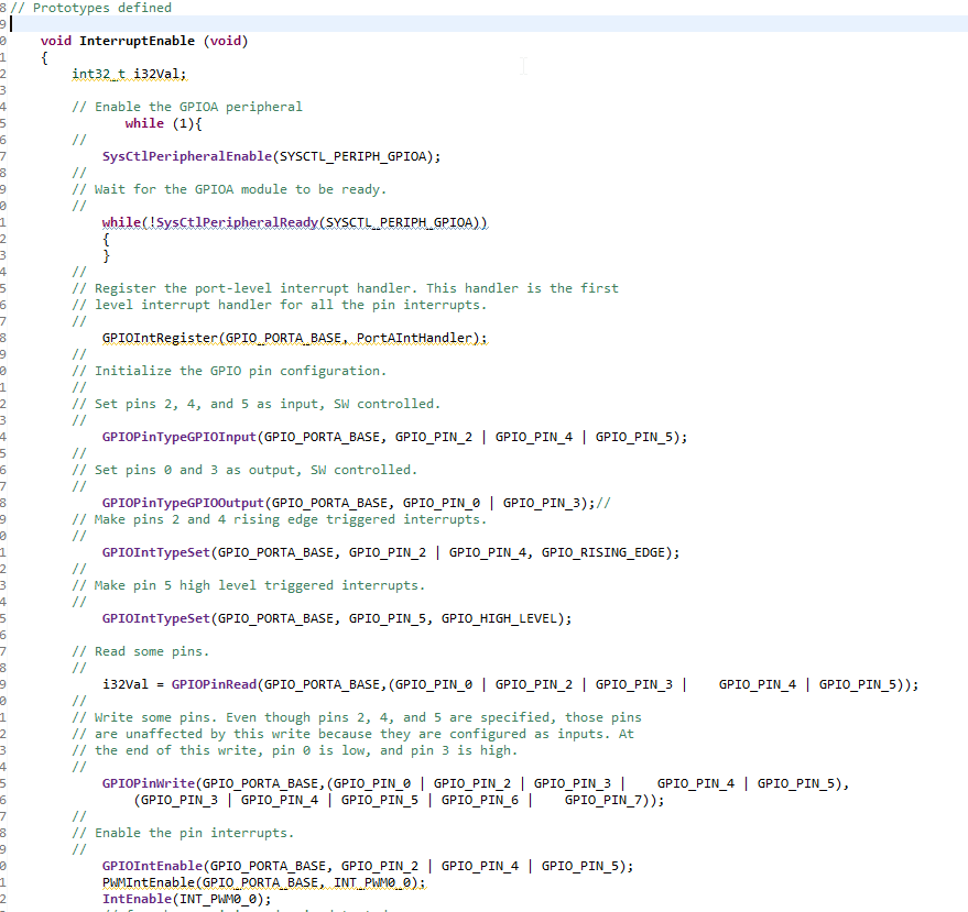
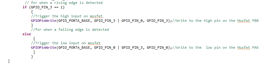
Here is the interrupt function I am calling.....

  • So I also noticed that I don't have an ISR defined, which might be a large part of my problem.

    How would I go about writing an ISR for this function?
  • Hello Rachel,

    You mentioned producing most of that from sample code, but have you studied the Interrupts example in TivaWare for your LaunchPad? It can be found at [Install Path]\TivaWare_C_Series-2.1.4.178\examples\boards\ek-tm4c123gxl\interrupts. That would at least show you how to make ISR's. For ISR's you also need to add them to the startup_ccs.c file so they are associated with the interrupt vector table. The interrupts example will also show you how to do this.

    You definitely need the ISR to have this function right and I was going to ask where that is.

    I would also say you have too much going on right now if you are just learning interrupts. Try and simplify your code. See if you get an interrupt to trigger on a single GPIO first, and then add in further functionality.

    You will need to call IntMasterEnable to enable interrupts as a whole, and then use IntEnable for each interrupt vector you want to trigger interrupts on. Those are the biggest things I see missing at a first glance.

    Try and look at that example and make your ISR, and then if you are still having problems, re-post your code including the ISR. By the way you can just post the code on E2E without screenshots by clicking the </> symbol in the same editor you used to add the pictures.
  • Hi Ralph,

    Thank you for all the information it was very very helpful.

    I have looked through the example and see have seen some points where I went wrong.

    I have also simplified my code to just output to one single GPIO right now.

    However, this code is still running infinitely when I debug it so it may be triggering a fault ISR.

    Thank you for your help.

    ISR Code:

            void
            IntGPIOA(void)
                {
                    int i = 0;
                    int ui32Loop;
                    //
                    // Set PE1 high to indicate entry to this interrupt handler.
                    //
                    ROM_GPIOPinWrite(GPIO_PORTE_BASE, GPIO_PIN_1, GPIO_PIN_1);
    
                    //
                    // Put the current interrupt state on the UART.
                    //
                    DisplayIntStatus();
                    //Trigger interrupt A
                    HWREG(NVIC_SW_TRIG) = INT_GPIOA- 16;
    
                    //
                    // Wait two seconds.
                    //
                    for(ui32Loop = 0; ui32Loop < 200000; ui32Loop++)
                    {
                    }
                    //
                    // Save and increment the interrupt sequence number.
                    //
                    g_ui32GPIOA = g_ui32Index++;
    
                    //
                    // Set PE1 low to indicate exit from this interrupt handler.
                    //
                    ROM_GPIOPinWrite(GPIO_PORTE_BASE, GPIO_PIN_1, 0);
                }

    Main Function Code:

      void InterruptEnable (void)
        {
            int32_t i32Val;
    
            ROM_IntMasterEnable();
    
            ROM_IntEnable(INT_GPIOA);
            //ROM_IntEnable(INT_GPIOB);
    
            // Enable the GPIOA peripheral
                   while (1){
            //
                SysCtlPeripheralEnable(SYSCTL_PERIPH_GPIOA);
            //
            // Wait for the GPIOA module to be ready.
            //
                while(!SysCtlPeripheralReady(SYSCTL_PERIPH_GPIOA))
                {
                }
            //
            // Register the port-level interrupt handler. This handler is the first
            // level interrupt handler for all the pin interrupts.
            //
                GPIOIntRegister(GPIO_PORTA_BASE, IntGPIOA);
            //
            // Initialize the GPIO pin configuration.
            //
            // Set pins 2, 4, and 5 as input, SW controlled.
            //
                GPIOPinTypeGPIOInput(GPIO_PORTA_BASE, GPIO_PIN_2); //| GPIO_PIN_4 | GPIO_PIN_5);
            //
            // Set pins 0 and 3 as output, SW controlled.
            //
                GPIOPinTypeGPIOOutput(GPIO_PORTA_BASE, GPIO_PIN_0);// | GPIO_PIN_3);//
            // Make pins 2 and 4 rising edge triggered interrupts.
            //
               // GPIOIntTypeSet(GPIO_PORTA_BASE, GPIO_PIN_2 | GPIO_PIN_4, GPIO_RISING_EDGE);
            //
            // Make pin 5 high level triggered interrupts.
            //
                //GPIOIntTypeSet(GPIO_PORTA_BASE, GPIO_PIN_5, GPIO_HIGH_LEVEL);
    
            // Read some pins.
            //
                i32Val = GPIOPinRead(GPIO_PORTA_BASE,(GPIO_PIN_2));//GPIO_PIN_0 | GPIO_PIN_2 | GPIO_PIN_3 |    GPIO_PIN_4 | GPIO_PIN_5));
            //
            // Write some pins. Even though pins 2, 4, and 5 are specified, those pins
            // are unaffected by this write because they are configured as inputs. At
            // the end of this write, pin 0 is low, and pin 3 is high.
            //
                GPIOPinWrite(GPIO_PORTA_BASE,(GPIO_PIN_0| GPIO_PIN_3 | GPIO_PIN_4 | GPIO_PIN_5),
                   (GPIO_PIN_3 | GPIO_PIN_4 | GPIO_PIN_5 | GPIO_PIN_6 |    GPIO_PIN_7));
            //
            // Enable the pin interrupts.
            //
                GPIOIntEnable(GPIO_PORTA_BASE, GPIO_PIN_2);// | GPIO_PIN_4 | GPIO_PIN_5);
                PWMIntEnable(GPIO_PORTA_BASE, INT_PWM0_0);
                IntEnable(INT_PWM0_0);
                // for when a rising edge is detected
              // if (GPIO_PIN_3 == 1)
                  // {
                 //  //Trigger the high input on mosfet
                   //GPIOPinWrite(GPIO_PORTA_BASE, GPIO_PIN_3 | GPIO_PIN_0, GPIO_PIN_3);//Write to the high pin on the Mosfet PB0
                  // }
                   //for when a falling edge is detected
              // else
                  //  {
                   //Trigger the low input on mosfet
                 //  GPIOPinWrite(GPIO_PORTA_BASE, GPIO_PIN_0 | GPIO_PIN_3, GPIO_PIN_0);//Write to the  low pin on the Mosfet PA6
                 //   }
                //   }
                   }
        }

  • Hello Rachel,

    I do not see a GPIOIntTypeSet API to configure what kind of signal would trigger the interrupt.

    Also, you wouldn't need the interrupt trigger in your ISR because you'd already be in it. That trigger may actually be what's locking the ISR up. In the example, GPIO B would trigger A, but in this case GPIO A is triggering A and may be causing a loop. Please take that out and see if the ISR starts working.

    Also regarding the ISR, since it looks like you copied the TIvaWare example - unfortunately while it's helpful for configuration, the TivaWare example is actually showing off multiple bad practices for ISR's.

    For a practical application, you should not be waiting 2 seconds in an ISR. If you need to measure something via a delay, use a timer that is triggered to start counting in the ISR and then promptly exit from the ISR. I didn't write the TivaWare example that does the 2 second delay and do not approve of that aspect of it's usage.

    On that same train of thought, I also would not do any UART communication in an ISR either. You want your ISR to resolve in as few cycles as you can manage reasonably, so anything with delays or using communication peripherals should all be address outside of the ISR. Rather you should read the result and many any quick decisions on what to do with the result in the ISR and then exit the ISR. I would reduce your ISR by getting rid of that stuff for now because it doesn't benefit you.

    Just general advice so hopefully our TivaWare example doesn't give you the wrong impressions... (I really wish I knew who thought it was a good idea to use bad ISR practices for a key example...)