Part Number: TM4C1294NCPDT
Other Parts Discussed in Thread: TM4C129XNCZAD
Hi,
We're trying to figure out how to configure the EPI from TM4C1294NCPDT to interface with the LCD controller SSD1926, from Solomon Systech.
We're only concerned with Write cycles, not interested in reading from LCD.
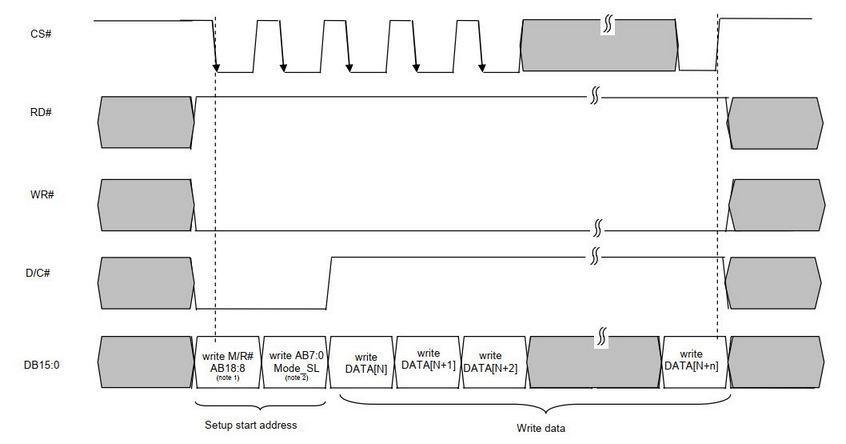
The picture below shows the Write cycle interface timing required from SSD1926.
Based on that diagram, we designed a custom hardware that has the following connections:
(MCU) ----------------- (SSD1926)
EPI0 28 WR --------- WE0#
EPI0 29 RD ---------- RD#
EPI0 30 ALE -------- D/C#
EPI0 31 CLK -------- CS#
EPI0 15:0 ------------ DB15:0
Is it possible to configure the EPI to implement this kind of cycle?
If yes, which EPI mode should be set? Is it Host Bus mode or General-Purpose mode? (It looks like Host Bus, but we're not sure).
Also, it's not clear how the SSD1926 will be mapped into the MCU memory map and how's the code to actually write data on the bus.
Is there an example similar to what we have here? We only found examples with SDRAM, and that's a very different application.
PS: we already have this working with GPIO "hard-coded" functions, but that's a very slow, cumbersome and sub-optimal solution, and makes LCD update very slow.
Best regards!