Part Number: TM4C129ENCPDT
Tool/software: TI C/C++ Compiler
Hi,
I am configuring Port M pins to be output pins so that I can output some pulses to an external ADC chip.
I have configured the port as shown in the following, there is no compiler error or warning however I can not see any pulses on PM4 and PM5 pins.
int main(void)
 {
    // Initialize system clock to 120 MHz
   // uint32_t ui32SysClock;
    ui32SysClock = ROM_SysCtlClockFreqSet(
                               (SYSCTL_XTAL_25MHZ | SYSCTL_OSC_MAIN |
                                SYSCTL_USE_PLL | SYSCTL_CFG_VCO_480),
                               SYSTEM_CLOCK);
    ASSERT(ui32SysClock == SYSTEM_CLOCK);

    // Initialize all peripherals i.e. LEDs, user buttons and UART0 connected to the Launchpad except USB and Ethernet
    PinoutSet(false, false);

    //Initialize System
    sys_init();


    // Create tasks

    xTaskCreate(demoLEDTask, (const portCHAR *)"LEDs",
                configMINIMAL_STACK_SIZE, NULL, 1, NULL);

    xTaskCreate(SerialTask, (const portCHAR *)"Serial",
                configMINIMAL_STACK_SIZE, NULL, 1, NULL);

    xTaskCreate(spi0_receive, (const portCHAR *)"SPI0",
                configMINIMAL_STACK_SIZE, NULL, 3, NULL);
    xTaskCreate(adc_start, (const portCHAR *)"ADCSTART",
                configMINIMAL_STACK_SIZE, NULL, 2, NULL);

    vTaskStartScheduler();
    return 0;
}

void sys_init(void)
{
    uint32_t i;

        //Set up the UART which is connected to the virtual COM port
        UARTStdioConfig(0, 57600, SYSTEM_CLOCK);
        //
        // The SSI0 peripheral must be enabled for use.
        //
        SysCtlPeripheralEnable(SYSCTL_PERIPH_SSI0);
        SysCtlPeripheralEnable(SYSCTL_PERIPH_GPIOA);
        SysCtlPeripheralEnable(SYSCTL_PERIPH_GPIOM);
.....
The Pins definitions and PORT INIT function;
Please note this is an external ADC Chip ans should not be confused with internal ADC of the ucontroller.
#define ADC_OS0                 GPIO_PIN_0 //PM0
#define ADC_OS1                 GPIO_PIN_1 //PM1
#define ADC_OS2                 GPIO_PIN_2 //PM2
#define ADC_BUSY                GPIO_PIN_3 //PM3
#define ADC_CNVSTARTA           GPIO_PIN_4 //PM4
#define ADC_CNVSTARTB           GPIO_PIN_5 //PM5
#define ADC_RANGE               GPIO_PIN_6 //PM6
#define ADC_RESET               GPIO_PIN_7 //PM7

#define ADC_CS                  GPIO_PIN_2 //PN2
#define ADC_READ                GPIO_PIN_3 //PN3

#define ADC_CTRL1_PORT          GPIO_PORTM_BASE
#define ADC_CTRL2_PORT          GPIO_PORTN_BASE
#define ADC_LSB_PORT            GPIO_PORTD_BASE
#define ADC_MSB_PORT            GPIO_PORTK_BASE


void adc_init(void)
{
    ROM_GPIOPinTypeGPIOOutput(ADC_CTRL1_PORT, ADC_OS0 | ADC_OS1 | ADC_OS2 | ADC_CNVSTARTA | ADC_CNVSTARTB | ADC_RANGE | ADC_RESET);
    ROM_GPIOPinTypeGPIOOutput(ADC_CTRL2_PORT, ADC_CS | ADC_READ);

    ROM_GPIOPinTypeGPIOInput(ADC_CTRL1_PORT, ADC_BUSY); //Configured ADC_BUSY pin as input
    ROM_GPIOPinTypeGPIOInput(ADC_MSB_PORT, 0xFF); //Configured ADC MSB Data Pins as input
    ROM_GPIOPinTypeGPIOInput(ADC_LSB_PORT, 0xFF); //Configured ADC LSB Data Pins as input

    GPIOPadConfigSet(ADC_CTRL1_PORT, ADC_CNVSTARTA | ADC_CNVSTARTB,
                     GPIO_STRENGTH_2MA, GPIO_PIN_TYPE_STD);


}

void adc_start (void *pvParameters)
{
    uint32_t i;
    for(;;)
    {
        GPIOPinWrite(ADC_CTRL1_PORT,ADC_CNVSTARTA,0x0);
        GPIOPinWrite(ADC_CTRL1_PORT,ADC_CNVSTARTB,0x0);
        for(i=0;i<42949;i++){}
        GPIOPinWrite(ADC_CTRL1_PORT,ADC_CNVSTARTA,0x1);
        GPIOPinWrite(ADC_CTRL1_PORT,ADC_CNVSTARTB,0x1);

        vTaskDelay(1000);

    }


}
I dont know what, I am missing ?
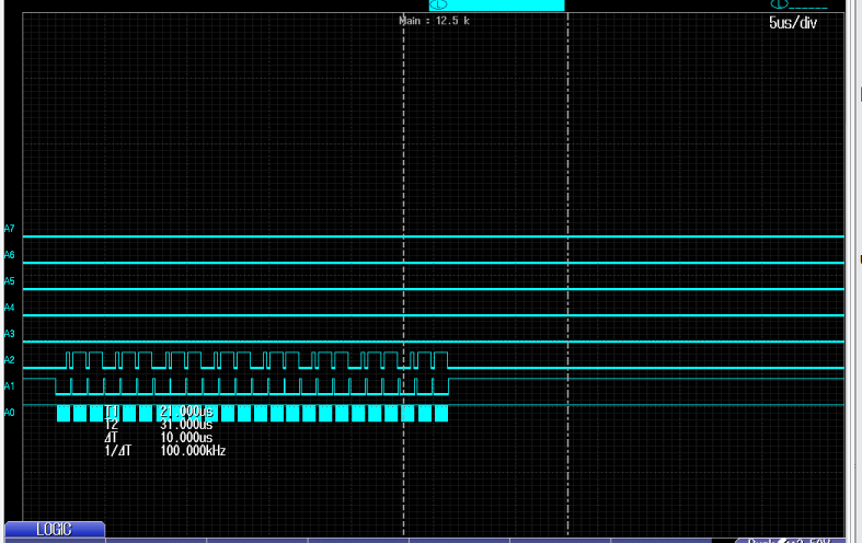
Following is the snapshot of my logic analyzer, showing A3 and A4 (connected to PM4 and PM5 respectively) are low.