This thread has been locked.

If you have a related question, please click the "Ask a related question" button in the top right corner. The newly created question will be automatically linked to this question.

TM4C129ENCPDT: GPIO Toggling very slow

Part Number: TM4C129ENCPDT

Hi,

I am trying to toggle a GPIO Pin and it seems to be extremely slow.

My ucontroller main clock is at 120MHz.

I deleted the in-between delay but still it is ver slow.

Here is how my clock is configured. I have verified the clock is at 120MHz by reading uint32_t sys_clock.

// Initialize system clock to 120 MHz
   // uint32_t sys_clock;
    sys_clock = ROM_SysCtlClockFreqSet(
                               (SYSCTL_XTAL_25MHZ | SYSCTL_OSC_MAIN |
                                SYSCTL_USE_PLL | SYSCTL_CFG_VCO_480),
                               SYSTEM_CLOCK);
    ASSERT(sys_clock == SYSTEM_CLOCK);


And the code for toggling the Pins;

void adc_conv_start (void)
{
        GPIOPinWrite(ADC_CTRL1_PORT,ADC_CNVSTARTA |ADC_CNVSTARTB ,0);
        //for(i=0;i<1;i++){}
        //SysCtlDelay(1);
        GPIOPinWrite(ADC_CTRL1_PORT, ADC_CNVSTARTA | ADC_CNVSTARTB, ADC_CNVSTARTA | ADC_CNVSTARTB);
}

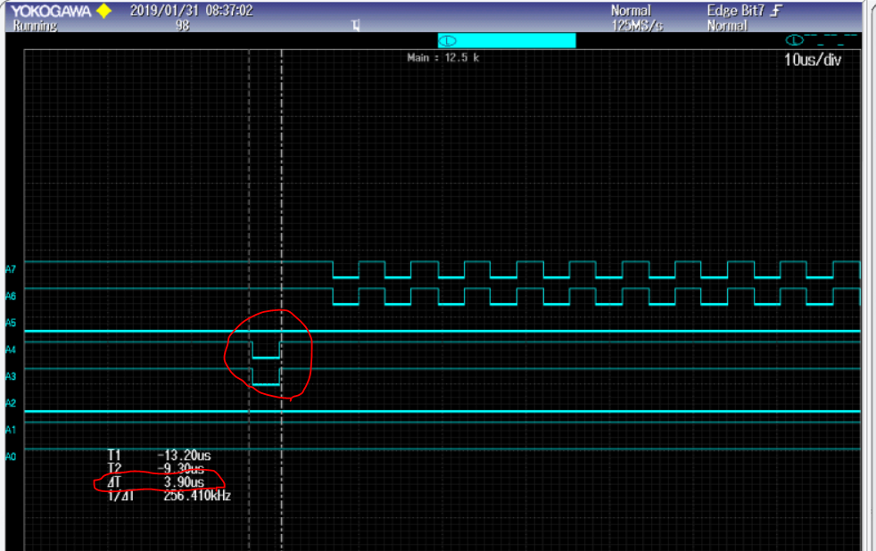
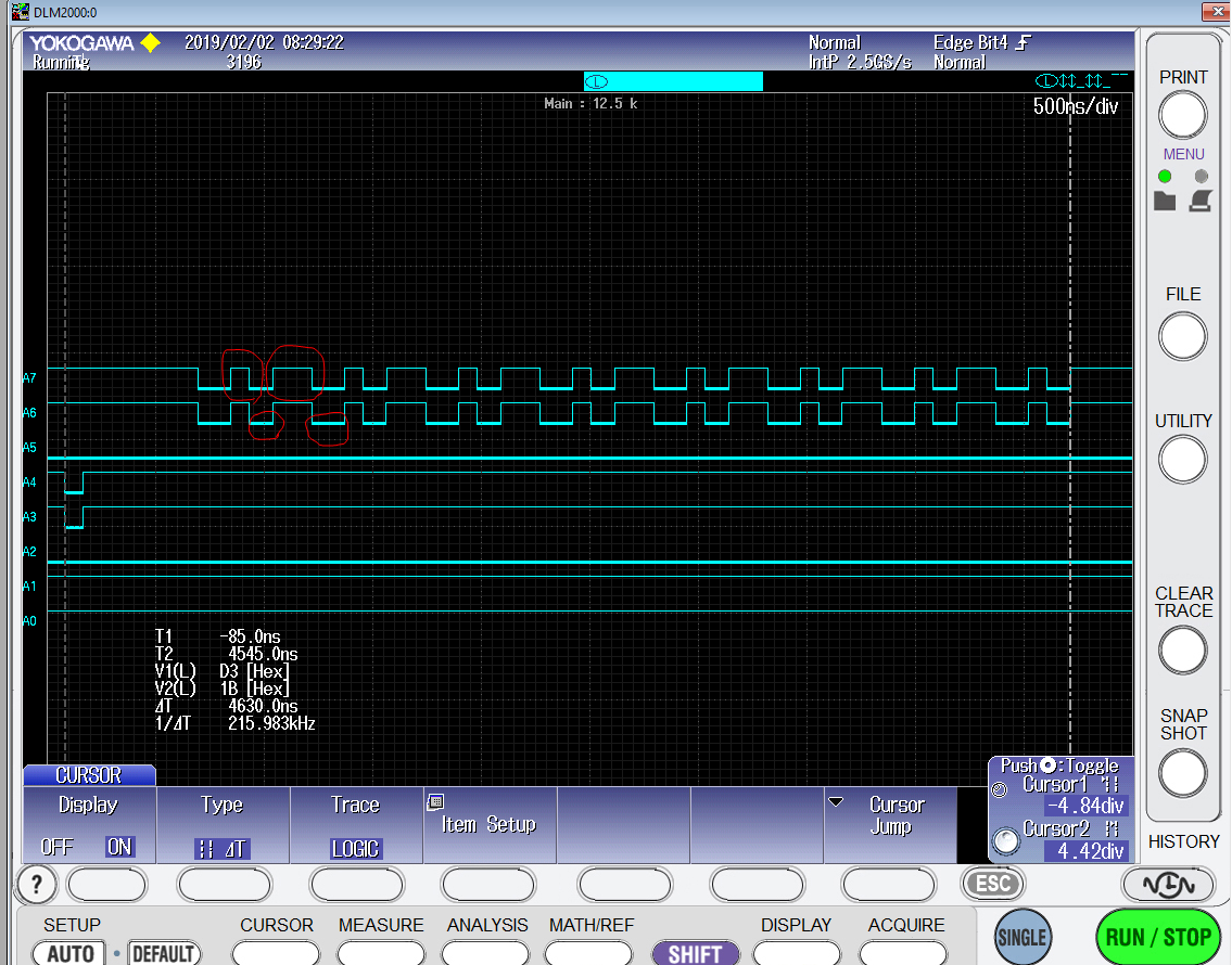
And here is the snapshot from the scope showing a delay of 3.9 usec.

  • Hello Sahil,

    I agree that is quite slow, do you have any interrupts or other processes running which could be occupying the MCU?

    Can you try using your clock setting API with our blinky project, remove the delay loops in main(), and report back the result you see there? If we see the higher speed toggling in that case, that would indicate that something is triggering from your GPIO and causing the delay. You may want to change the pin from N0 to something easily accessible like N2 for this test.

  • Hello Ralph,

    I can try that as well but here I am running FreeRTOS with tick rate set to 100Hz only.
    Plus my GPIO toggling is directly inside the interrupt. There is no interrupt other than the systick running at 100Hz and the timer0A interrupt at 10Hz.

    Here is the whole picture;

    #include <stdint.h>
    #include <stdbool.h>
    #include "main.h"
    #include "drivers/pinout.h"
    #include "utils/uartstdio.h"


    // TivaWare includes
    #include "driverlib/sysctl.h"
    #include "driverlib/debug.h"
    #include "driverlib/rom.h"
    #include "driverlib/rom_map.h"
    #include "driverlib/inc/hw_memmap.h"
    #include "driverlib/gpio.h"
    #include "driverlib/pin_map.h"
    #include "driverlib/ssi.h"
    #include "driverlib/inc/hw_ssi.h"
    #include "driverlib/inc/hw_types.h"
    #include "driverlib/timer.h"
    #include "driverlib/interrupt.h"
    #include "driverlib/tm4c129encpdt.h"

    // FreeRTOS includes
    #include "FreeRTOSConfig.h"
    #include "FreeRTOS.h"
    #include "task.h"
    #include "queue.h"

    #define NUM_SSI_DATA 3

    //General Functions declarations
    void adc_init(void);
    void sys_init(void);
    void timer0_init(void);
    void adc_collect_data(void);
    void adc_conv_start (void);

    // FreeRTOS Tasks declarations
    void blinkLED0_Task(void *pvParameters);
    void SerialTask(void *pvParameters);
    void Timer0IntTask(void *pvParameters);


    //FreeRTOS Handles
    TaskHandle_t Timer0IntTask_Handle;


    void spi0_transmit (void *pvParameters);


    volatile uint32_t sys_clock;
    volatile uint32_t counter;
    volatile uint32_t ch0,ch1,ch2,ch3,ch4,ch5,ch6,ch7;

    //uint32_t data[16];
    union {
    uint32_t ui32value[8];
    uint8_t ui8byte[32];
    }data;
    // Main function
    int main(void)
    {
    // Initialize system clock to 120 MHz
    // uint32_t sys_clock;
    sys_clock = ROM_SysCtlClockFreqSet(
    (SYSCTL_XTAL_25MHZ | SYSCTL_OSC_MAIN |
    SYSCTL_USE_PLL | SYSCTL_CFG_VCO_480),
    SYSTEM_CLOCK);
    ASSERT(sys_clock == SYSTEM_CLOCK);


    // Initialize all peripherals i.e. LEDs, user buttons and UART0 connected to the Launchpad except USB and Ethernet
    PinoutSet(false, false);

    //Initialize System
    sys_init();


    // Create tasks

    xTaskCreate(blinkLED0_Task, (const portCHAR *)"BLNKLED0",
    configMINIMAL_STACK_SIZE, NULL, 1, NULL);

    xTaskCreate(SerialTask, (const portCHAR *)"Serial",
    configMINIMAL_STACK_SIZE, NULL, 1, NULL);

    xTaskCreate(spi0_transmit, (const portCHAR *)"SPI0",
    configMINIMAL_STACK_SIZE, NULL, 2, NULL);

    xTaskCreate(Timer0IntTask, (const portCHAR *)"Timer0IntTask",
    configMINIMAL_STACK_SIZE, NULL, 3, &Timer0IntTask_Handle);

    vTaskStartScheduler();
    return 0;
    }


    // Blink the LED0 on the launchpad
    void blinkLED0_Task(void *pvParameters)
    {
    for (;;)
    {
    GPIOPinWrite(LED0_PORT,LED0,LED0);
    vTaskDelay(500);
    GPIOPinWrite(LED0_PORT,LED0,0);
    vTaskDelay(500);

    }
    }

    // Blink the LED1 on the launchpad
    void blinkLED1_Task(void *pvParameters)
    {
    for (;;)
    {
    GPIOPinWrite(LED1_PORT,LED1,LED1);
    vTaskDelay(500);
    GPIOPinWrite(LED1_PORT,LED1,0);
    vTaskDelay(500);

    }
    }
    // Blink the LED2 on the launchpad
    void blinkLED2_Task(void *pvParameters)
    {
    for (;;)
    {
    GPIOPinWrite(LED2_PORT,LED2,LED2);
    vTaskDelay(500);
    GPIOPinWrite(LED2_PORT,LED2,0);
    vTaskDelay(500);

    }
    }

    // Blink the LED3 on the launchpad
    void blinkLED3_Task(void *pvParameters)
    {
    for (;;)
    {
    GPIOPinWrite(LED3_PORT,LED3,LED3);
    vTaskDelay(500);
    GPIOPinWrite(LED3_PORT,LED3,0);
    vTaskDelay(500);

    }
    }
    // Write text over the Stellaris debug interface UART port
    void SerialTask(void *pvParameters)
    {


    for (;;)
    {
    UARTprintf("\r\nSystem Clock:\t\t%dMHz",sys_clock/1000000);
    //UARTprintf("\r\ndata.ui32value[0] = 0x%X, data.ui8byte[3] = 0x%X, data.ui8byte[2] = 0x%X, data.ui8byte[1] = 0x%X, data.ui8byte[0] = 0x%X",data.ui32value[0],data.ui8byte[3],data.ui8byte[2],data.ui8byte[1],data.ui8byte[0]);

    vTaskDelay(1000 / portTICK_PERIOD_MS);

    }
    }

    void sys_init(void)
    {
    uint32_t i;

    //Set up the UART which is connected to the virtual COM port
    UARTStdioConfig(UART0, UART0_BAUD_RATE, SYSTEM_CLOCK);
    //
    // The SSI0 peripheral must be enabled for use.
    //
    SysCtlPeripheralEnable(SYSCTL_PERIPH_SSI0);
    SysCtlPeripheralEnable(SYSCTL_PERIPH_GPIOA);
    SysCtlPeripheralEnable(SYSCTL_PERIPH_GPIOM);
    SysCtlPeripheralEnable(SYSCTL_PERIPH_GPION);

    //
    // Configure the pin muxing for SSI0 functions on port A2, A3, A4, and A5.
    // This step is not necessary if your part does not support pin muxing.
    // TODO: change this to select the port/pin you are using.
    //
    GPIOPinConfigure(GPIO_PA2_SSI0CLK);
    GPIOPinConfigure(GPIO_PA3_SSI0FSS);
    GPIOPinConfigure(GPIO_PA4_SSI0RX);
    GPIOPinConfigure(GPIO_PA5_SSI0TX);

    //
    // Configure the GPIO settings for the SSI pins. This function also gives
    // control of these pins to the SSI hardware. Consult the data sheet to
    // see which functions are allocated per pin.
    // The pins are assigned as follows:
    // PA5 - SSI0Tx
    // PA4 - SSI0Rx
    // PA3 - SSI0Fss
    // PA2 - SSI0CLK
    // TODO: change this to select the port/pin you are using.
    //
    GPIOPinTypeSSI(GPIO_PORTA_BASE, GPIO_PIN_5 | GPIO_PIN_4 | GPIO_PIN_3 |
    GPIO_PIN_2);

    #if defined(TARGET_IS_TM4C129_RA0) || \
    defined(TARGET_IS_TM4C129_RA1) || \
    defined(TARGET_IS_TM4C129_RA2)
    SSIConfigSetExpClk(SSI0_BASE, sys_clock, SSI_FRF_MOTO_MODE_2,
    SSI_MODE_MASTER, SPI0_CLK_SPEED, SPI0_DATA_WIDTH);
    #else
    SSIConfigSetExpClk(SSI0_BASE, SysCtlClockGet(), SSI_FRF_MOTO_MODE_0,
    SSI_MODE_MASTER, 1000000, 8);
    #endif
    // Enable the SSI0 module.
    //
    SSIEnable(SSI0_BASE);
    adc_init();
    timer0_init();


    for (i=0;i<8;i++){data.ui32value[i] = 0x3FFFF;} //Fill the array with some data for simulation purpose only


    }


    void spi0_transmit (void *pvParameters)
    {
    //uint32_t data[8], temp1;
    uint8_t i;

    for (;;)
    {
    //
    // Display indication that the SSI is transmitting data.
    //
    //UARTprintf("'\r\n0x%X sent to MOSI' ", counter);


    for (i = 0;i<1;i++)
    {

    //data ui32value 0
    SSIDataPut(SSI0_BASE, data.ui8byte[2]); //MSB
    SSIDataPut(SSI0_BASE, data.ui8byte[1]);
    SSIDataPut(SSI0_BASE, data.ui8byte[0]); //LSB

    //data ui32value 1
    SSIDataPut(SSI0_BASE, data.ui8byte[6]);
    SSIDataPut(SSI0_BASE, data.ui8byte[5]);
    SSIDataPut(SSI0_BASE, data.ui8byte[4]);

    //data ui32value 2
    SSIDataPut(SSI0_BASE, data.ui8byte[10]);
    SSIDataPut(SSI0_BASE, data.ui8byte[9]);
    SSIDataPut(SSI0_BASE, data.ui8byte[8]);

    //data ui32value 3
    SSIDataPut(SSI0_BASE, data.ui8byte[10]);
    SSIDataPut(SSI0_BASE, data.ui8byte[9]);
    SSIDataPut(SSI0_BASE, data.ui8byte[8]);

    //data ui32value 4
    SSIDataPut(SSI0_BASE, data.ui8byte[2]); //MSB
    SSIDataPut(SSI0_BASE, data.ui8byte[1]);
    SSIDataPut(SSI0_BASE, data.ui8byte[0]); //LSB

    //data ui32value 5
    SSIDataPut(SSI0_BASE, data.ui8byte[6]);
    SSIDataPut(SSI0_BASE, data.ui8byte[5]);
    SSIDataPut(SSI0_BASE, data.ui8byte[4]);

    //data ui32value 6
    SSIDataPut(SSI0_BASE, data.ui8byte[10]);
    SSIDataPut(SSI0_BASE, data.ui8byte[9]);
    SSIDataPut(SSI0_BASE, data.ui8byte[8]);

    //data ui32value 7
    SSIDataPut(SSI0_BASE, data.ui8byte[10]);
    SSIDataPut(SSI0_BASE, data.ui8byte[9]);
    SSIDataPut(SSI0_BASE, data.ui8byte[8]);


    //while(SSIBusy(SSI0_BASE)){}
    //SSIDataGetNonBlocking(SSI0_BASE, &data[i]); //(0b01000101 << 8) = (0b100010100000000)

    }
    //while(SSIBusy(SSI0_BASE)){}

    vTaskDelay(1000);

    }


    }

    void adc_init(void)
    {
    ROM_GPIOPinTypeGPIOOutput(ADC_CTRL1_PORT, ADC_OS0 | ADC_OS1 | ADC_OS2 | ADC_CNVSTARTA | ADC_CNVSTARTB | ADC_RANGE | ADC_RESET);
    ROM_GPIOPinTypeGPIOOutput(ADC_CTRL2_PORT, ADC_CS | ADC_READ);

    ROM_GPIOPinTypeGPIOInput(ADC_CTRL1_PORT, ADC_BUSY); //Configured ADC_BUSY pin as input
    ROM_GPIOPinTypeGPIOInput(ADC_MSB_PORT, 0xFF); //Configured ADC MSB Data Pins as input
    ROM_GPIOPinTypeGPIOInput(ADC_LSB_PORT, 0xFF); //Configured ADC LSB Data Pins as input

    GPIOPadConfigSet(ADC_CTRL1_PORT, ADC_CNVSTARTA | ADC_CNVSTARTB,GPIO_STRENGTH_2MA, GPIO_PIN_TYPE_STD);

    GPIOPinWrite(ADC_CTRL2_PORT,ADC_CS | ADC_READ, ADC_CS | ADC_READ); //Pull ADC_CS and ADC_READ High
    GPIOPinWrite(ADC_CTRL1_PORT, ADC_CNVSTARTA | ADC_CNVSTARTB, ADC_CNVSTARTA | ADC_CNVSTARTB);


    }

    void adc_conv_start (void)
    {
    GPIOPinWrite(ADC_CTRL1_PORT,ADC_CNVSTARTA |ADC_CNVSTARTB ,0);
    //for(i=0;i<1;i++){}
    //SysCtlDelay(1);
    GPIOPinWrite(ADC_CTRL1_PORT, ADC_CNVSTARTA | ADC_CNVSTARTB, ADC_CNVSTARTA | ADC_CNVSTARTB);
    }

    void adc_collect_data(void)
    {
    uint32_t i = 0, ch = 0;
    adc_conv_start();
    if ((GPIOPinRead(ADC_CTRL1_PORT,ADC_BUSY) != 0) & (i != 600)) {i++;}

    //Read ADC Channel 0
    for(ch=0;ch<8;ch++)
    {
    GPIOPinWrite(ADC_CTRL2_PORT,ADC_CS | ADC_READ, 0); //Pull ADC_CS and ADC_READ Low to read MSB 16bits
    //data.ui32value[ch] = (((GPIOPinRead(ADC_MSB_PORT,0xFF)) & 0xFF) | (0xFF)); //Read all 8 Pins (((GPIOPinRead(ADC_MSB_PORT,0xFF)) & 0xFF) | (0xFF));
    //UARTprintf("\r\nvalue before shift left: 0x%X",data.ui32value[ch]);
    //data.ui32value[ch] = data.ui32value[ch] << 8;
    //UARTprintf("\r\nvalue after shift left: 0x%X",data.ui32value[ch]);
    //data.ui32value[ch] |=(((GPIOPinRead(ADC_LSB_PORT,0xFF)) & 0xFF) | (0xFF)); //Read all 8 Pins (((GPIOPinRead(ADC_LSB_PORT,0xFF)) & 0xFF) | (0xFF));
    //UARTprintf("\r\nvalue before second shift left: 0x%X",data.ui32value[ch]);
    GPIOPinWrite(ADC_CTRL2_PORT,ADC_CS | ADC_READ, ADC_CS | ADC_READ); //Pull ADC_CS and ADC_READ High
    //data.ui32value[ch] = data.ui32value[ch] << 2;
    //UARTprintf("\r\nvalue after second shift left: 0X%x",data.ui32value[ch]);
    GPIOPinWrite(ADC_CTRL2_PORT,ADC_CS | ADC_READ, 0); //Pull ADC_CS and ADC_READ Low to read remaining 2 LSB bits
    //data.ui32value[ch] |= (((GPIOPinRead(ADC_LSB_PORT,0x3)) & 0x3) | (0x3)); //Read 2 LSBs the 17th and 18th bits of the ADC
    //UARTprintf("\r\nvalue after full adjustment: 0X%x",data.ui32value[ch]);
    GPIOPinWrite(ADC_CTRL2_PORT,ADC_CS | ADC_READ, ADC_CS | ADC_READ); //Pull ADC_CS and ADC_READ High
    }

    }


    void timer0_init(void)
    {
    uint32_t ui32Period;
    ROM_SysCtlPeripheralEnable(SYSCTL_PERIPH_TIMER0);
    TimerConfigure(TIMER0_BASE, TIMER_CFG_PERIODIC);

    //ui32Period = (sys_clock / 10) / 2;
    ui32Period = (sys_clock / 100);
    UARTprintf("\r\nPeriod = %d",ui32Period);

    TimerLoadSet(TIMER0_BASE, TIMER_A, ui32Period -1);

    IntEnable(INT_TIMER0A);

    TimerIntEnable(TIMER0_BASE, TIMER_TIMA_TIMEOUT);

    IntMasterEnable();

    TimerEnable(TIMER0_BASE, TIMER_A);

    }

    void Timer0IntHandler(void)
    {
    // Clear the timer interrupt
    TimerIntClear(TIMER0_BASE, TIMER_TIMA_TIMEOUT);
    // Read the current state of the GPIO pin and
    // write back the opposite state
    adc_collect_data();
    BaseType_t checkIfYieldRequired;
    checkIfYieldRequired = xTaskResumeFromISR(Timer0IntTask_Handle);
    portYIELD_FROM_ISR(checkIfYieldRequired);
    //GPIOPinWrite(LED2_PORT,LED2,((~LED2) & 0x10));
    }

    void Timer0IntTask(void *pvParameters)
    {
    uint32_t i = 0;
    while(1)
    {
    vTaskSuspend(NULL); //suspend itself
    //adc_collect_data();


    //UARTprintf("\r\n%d Timer0IntTask\n\rdata.ui32value[0] = 0x%X, data.ui8byte[3] = 0x%X, data.ui8byte[2] = "
    //"0x%X, data.ui8byte[1] = 0x%X, data.ui8byte[0] = 0x%X",\
    i++,data.ui32value[0],data.ui8byte[3],data.ui8byte[2],data.ui8byte[1],data.ui8byte[0]);


    //UARTprintf("\r\n%d This is printing form Timer0IntTask",i++);

    }
    }


    /* ASSERT() Error function
    *
    * failed ASSERTS() from driverlib/debug.h are executed in this function
    */
    void __error__(char *pcFilename, uint32_t ui32Line)
    {
    // Place a breakpoint here to capture errors until logging routine is finished
    while (1)
    {
    }
    }
  • You can see the toggling is directly inside the interrupt routine;
    as shown bellow again;

    void Timer0IntHandler(void)
    {
    // Clear the timer interrupt
    TimerIntClear(TIMER0_BASE, TIMER_TIMA_TIMEOUT);
    adc_collect_data();
    BaseType_t checkIfYieldRequired;
    checkIfYieldRequired = xTaskResumeFromISR(Timer0IntTask_Handle);
    portYIELD_FROM_ISR(checkIfYieldRequired);
    //GPIOPinWrite(LED2_PORT,LED2,((~LED2) & 0x10));
    }
  • Note inside Timer0IntHandler (), adc_collect_data() is called which calls adc_conv_start(), It is this straight and simple function toggling the pins. as shown bellow;


    void adc_conv_start (void)
    {
    GPIOPinWrite(ADC_CTRL1_PORT,ADC_CNVSTARTA |ADC_CNVSTARTB ,0);
    //for(i=0;i<1;i++){}
    //SysCtlDelay(1);
    GPIOPinWrite(ADC_CTRL1_PORT, ADC_CNVSTARTA | ADC_CNVSTARTB, ADC_CNVSTARTA | ADC_CNVSTARTB);
    }
  • As you suggested. I tried the blinky project and It is working just fine as it takes 156nsec at 120MHz clock to toggle the LED without any delay loop in between setting the LED High and Low. I tried it with the Port M that I am using for toggling purpose and Port M is also toggling at 156nsec. This sounds good.

    Here is the snapshot;

    However, I still dont see any problem with my Project as there is no interrupt pulling the processor out.

    Since the project is standalone meaning that all the libraries are inside the project folder and doesnt require to adjust the compiler include paths or any additional work. It is just include and run kind of project. I am attaching as a zipped file here.

    3683.Project0.zip

  • Hello,

    I have further simplified my code by reducing it to a shorter program. Still no luck. I am highly doubting it has a relation with FreeRTOS.

    Here is the whole code;

    #include <stdint.h>
    #include <stdbool.h>
    #include "main.h"
    #include "drivers/pinout.h"
    #include "utils/uartstdio.h"
    
    
    // TivaWare includes
    #include "driverlib/sysctl.h"
    #include "driverlib/debug.h"
    #include "driverlib/rom.h"
    #include "driverlib/rom_map.h"
    #include "driverlib/gpio.h"
    #include "driverlib/inc/hw_memmap.h"
    // FreeRTOS includes
    #include "FreeRTOSConfig.h"
    #include "FreeRTOS.h"
    #include "task.h"
    #include "queue.h"
    
    #define SYSTEM_CLOCK    120000000U
    
    // Demo Task declarations
    void demoLEDTask(void *pvParameters);
    void demoSerialTask(void *pvParameters);
    
    // Main function
    int main(void)
    {
        // Initialize system clock to 120 MHz
        uint32_t output_clock_rate_hz;
        output_clock_rate_hz = ROM_SysCtlClockFreqSet(
                                   (SYSCTL_XTAL_25MHZ | SYSCTL_OSC_MAIN |
                                    SYSCTL_USE_PLL | SYSCTL_CFG_VCO_480),
                                   SYSTEM_CLOCK);
        ASSERT(output_clock_rate_hz == SYSTEM_CLOCK);
    
        // Initialize the GPIO pins for the Launchpad
        PinoutSet(false, false);
    
        ROM_GPIOPinTypeGPIOOutput(GPIO_PORTM_BASE, GPIO_PIN_4 | GPIO_PIN_5 );
        GPIOPadConfigSet(GPIO_PORTM_BASE, GPIO_PIN_4 | GPIO_PIN_5, GPIO_STRENGTH_2MA, GPIO_PIN_TYPE_STD);
        // Create demo tasks
        xTaskCreate(demoLEDTask, (const portCHAR *)"LEDs",
                    configMINIMAL_STACK_SIZE, NULL, 2, NULL);
    
        xTaskCreate(demoSerialTask, (const portCHAR *)"Serial",
                    configMINIMAL_STACK_SIZE, NULL, 1, NULL);
    
        vTaskStartScheduler();
        return 0;
    
    }
    
    
    // Flash the LEDs on the launchpad
    void demoLEDTask(void *pvParameters)
    {
    
        for (;;)
    
        {
            GPIOPinWrite(GPIO_PORTM_BASE,GPIO_PIN_4 |GPIO_PIN_5 ,0);
            //for(i=0;i<1;i++){}
            //SysCtlDelay(1);
            GPIOPinWrite(GPIO_PORTM_BASE, GPIO_PIN_4 | GPIO_PIN_5, GPIO_PIN_4 | GPIO_PIN_5);
    //        // Turn on LED 1
    //        LEDWrite(0x0F, 0x01);
    //        vTaskDelay(100);
    //
    //        // Turn on LED 2
    //        LEDWrite(0x0F, 0x02);
    //        vTaskDelay(100);
    //
    //        // Turn on LED 3
    //        LEDWrite(0x0F, 0x04);
    //        vTaskDelay(100);
    //
    //        // Turn on LED 4
    //        LEDWrite(0x0F, 0x08);
    //        vTaskDelay(100);
        }
    }
    
    
    // Write text over the Stellaris debug interface UART port
    void demoSerialTask(void *pvParameters)
    {
    
        // Set up the UART which is connected to the virtual COM port
        UARTStdioConfig(0, 57600, SYSTEM_CLOCK);
    
    
        for (;;)
        {
            UARTprintf("\r\nHello, world from FreeRTOS 9.0!");
            vTaskDelay(5000 / portTICK_PERIOD_MS);
        }
    }
    
    
    /*  ASSERT() Error function
     *
     *  failed ASSERTS() from driverlib/debug.h are executed in this function
     */
    void __error__(char *pcFilename, uint32_t ui32Line)
    {
        // Place a breakpoint here to capture errors until logging routine is finished
        while (1)
        {
        }
    }

    Any hint?

  • Hello Sahil,

    Thanks for posting the project. I am honestly unsure what is going on myself. I went through the Disassembly of your attached project and I don't see any additional interrupts or functions being called. Also modifying the tick length didn't impact the delay either.

    From everything I see, the MCU is executing the assembly code that has been programmed within it correctly, so from my standpoint unfortunately I have to disagree as the only thing I can possibly think is the issue here would how FreeRTOS operates as there is no indicators the MCU is not operating properly. Unfortunately we don't have enough experience with FreeRTOS to know exactly what is occurring that is interfering with the API.
  • Hello Ralph,

    Thanks for sparing your time.
    I would still like to keep this thread open at least for a while as I really need to get it fixed.
    I could remove the FreeRTOS from my project but I have to stick with FreeRTOS as I will later be implementing Telnet server as well.

    Will be great if Amit Ashara could help out.

    Thank you all
  • Hello Sahil,

    Unfortunately Amit moved to a different group within TI and no longer support TM4C MCU's :( We all miss his expertise.
  • I see.

    I have pm him, on his mercy.....

    Ralph I thank you very much any way.
  •  Hi,

    I have narrowed down the problem by commenting out most of the code. I have commented out all FreeRTOS includes. I have even disabled the systick  timer which is in port.c that runs the FreeRTOS scheduler and I have commented out the scheduler as well.  This way I have isolated the FreeRTOS part completely.

    I have simply put a while(1) loop as can be seen in the code. Now my code is very short but the problem is still there.

    Which indicates some thing with the void __error__(char *pcFilename, uint32_t ui32Line) function at the end of the code.

    However when I try to comment out this function the compiler gives me the following error.

    However, If I DO NOT comment out above function. It compiles without any error and produces the slow delay of 3.125usec. Also my project contains all the c files along with .h files inclusive and should not need driberlib.lib to be included in the linker path.

    Here is the code after commenting out all FreeRTOS stuff. The same project is attached with this message.

    #include <stdint.h>
    #include <stdbool.h>
    #include "main.h"
    #include "drivers/pinout.h"
    #include "utils/uartstdio.h"
    
    
    // TivaWare includes
    #include "driverlib/sysctl.h"
    //#include "driverlib/debug.h"
    #include "driverlib/rom.h"
    #include "driverlib/rom_map.h"
    #include "driverlib/gpio.h"
    #include "driverlib/inc/hw_memmap.h"
    // FreeRTOS includes
    //#include "FreeRTOSConfig.h"
    //#include "FreeRTOS.h"
    //#include "task.h"
    //#include "queue.h"
    
    
    // Demo Task declarations
    //void demoLEDTask(void *pvParameters);
    //void demoSerialTask(void *pvParameters);
    
    // Main function
    int main(void)
    {
        uint32_t i;
        i = 0;
        // Initialize system clock to 120 MHz
        uint32_t output_clock_rate_hz;
        output_clock_rate_hz = ROM_SysCtlClockFreqSet(
                                   (SYSCTL_XTAL_25MHZ | SYSCTL_OSC_MAIN |
                                    SYSCTL_USE_PLL | SYSCTL_CFG_VCO_480),
                                   SYSTEM_CLOCK);
        //ASSERT(output_clock_rate_hz == SYSTEM_CLOCK);
    
        // Initialize the GPIO pins for the Launchpad
        //PinoutSet(false, false);
        ROM_SysCtlPeripheralEnable(SYSCTL_PERIPH_GPIOM);
    
        ROM_GPIOPinTypeGPIOOutput(GPIO_PORTM_BASE, GPIO_PIN_4 | GPIO_PIN_5 );
        //GPIOPadConfigSet(GPIO_PORTM_BASE, GPIO_PIN_4 | GPIO_PIN_5, GPIO_STRENGTH_2MA, GPIO_PIN_TYPE_STD);
        // Create demo tasks
    //    xTaskCreate(demoLEDTask, (const portCHAR *)"LEDs", configMINIMAL_STACK_SIZE, NULL, 2, NULL);
    //
    //    xTaskCreate(demoSerialTask, (const portCHAR *)"Serial", configMINIMAL_STACK_SIZE, NULL, 1, NULL);
        while(1)
        {
            GPIOPinWrite(GPIO_PORTM_BASE,GPIO_PIN_4 |GPIO_PIN_5 ,0);
            //for(i=0;i<2;i++){}
            //SysCtlDelay();
            GPIOPinWrite(GPIO_PORTM_BASE, GPIO_PIN_4 | GPIO_PIN_5, GPIO_PIN_4 | GPIO_PIN_5);
        }
    
        //vTaskStartScheduler();
        return 0;
    
    }
    
    
    // Flash the LEDs on the launchpad
    //void demoLEDTask(void *pvParameters)
    //{
    //
    //    for (;;)
    //
    //    {
    //        GPIOPinWrite(GPIO_PORTM_BASE,GPIO_PIN_4 |GPIO_PIN_5 ,0);
    //        //for(i=0;i<1;i++){}
    //        //SysCtlDelay(1);
    //        GPIOPinWrite(GPIO_PORTM_BASE, GPIO_PIN_4 | GPIO_PIN_5, GPIO_PIN_4 | GPIO_PIN_5);
    //        // Turn on LED 1
    //        LEDWrite(0x0F, 0x01);
    //        vTaskDelay(100);
    //
    //        // Turn on LED 2
    //        LEDWrite(0x0F, 0x02);
    //        vTaskDelay(100);
    //
    //        // Turn on LED 3
    //        LEDWrite(0x0F, 0x04);
    //        vTaskDelay(100);
    //
    //        // Turn on LED 4
    //        LEDWrite(0x0F, 0x08);
    //        vTaskDelay(100);
    //    }
    //}
    
    
    // Write text over the Stellaris debug interface UART port
    //void demoSerialTask(void *pvParameters)
    //{
    //
    //    // Set up the UART which is connected to the virtual COM port
    //    UARTStdioConfig(0, 57600, SYSTEM_CLOCK);
    //
    //
    //    for (;;)
    //    {
    //        UARTprintf("\r\nHello, world from FreeRTOS 9.0!");
    //        vTaskDelay(5000 / portTICK_PERIOD_MS);
    //    }
    //}
    
    
    /*  ASSERT() Error function
     *
     *  failed ASSERTS() from driverlib/debug.h are executed in this function
     */
    void __error__(char *pcFilename, uint32_t ui32Line)
    {
        // Place a breakpoint here to capture errors until logging routine is finished
        while (1)
        {
        }
    }
    

    FreeRTOS_tiva_demo.zip

  • Hello,

    Sahil said:
    void adc_conv_start (void)
    {
    GPIOPinWrite(ADC_CTRL1_PORT,ADC_CNVSTARTA |ADC_CNVSTARTB ,0);
    //for(i=0;i<1;i++){}
    //SysCtlDelay(1);
    GPIOPinWrite(ADC_CTRL1_PORT, ADC_CNVSTARTA | ADC_CNVSTARTB, ADC_CNVSTARTA | ADC_CNVSTARTB);
    }

    Perhaps try static void for toggle function? Obviously it is being interrupted by another call between toggling or the OS task handler timer is running slower than the GPIO toggle rate. Note that toggling LED from NOT of bitwise &  "((~LED) & 0x10))" may produce unexpected results. The AND bitwise NOT "&(~pin)" should work to invert bits but CCS compiler never seems to invert the pin as expected. GPIOPinWrite() works much better with KISS approach of hex value only, no bitwise NOT or AND added to syntax.

  • Hello Sahil,

    Interesting results you came across. I went ahead and imported your project again and did some testing. It looks like if you remove the pre-defined symbol "DEBUG" the toggle time seems to be fine.

    What is strangest to me is that the __error__ function needs to be in your main.c file and that it won't see the driverlib debug file. I am not sure why this is the case. I think your project may have gotten corrupt in some manner.

    When I made a new project and copied your code, I no longer needed to have the __error__ in the main.c file - just having debug.h included was enough - and I was able to have the DEBUG pre-defined symbol included and still had the same rapid toggling of the GPIO (disclaimer: I didn't measure precisely if there was a small performance drop-off to add it).
  • Hi Ralph,

    Yes you are right, I also noticed the same.
    I also moved the code to a completely new clean project and now it is working fine. it is able to toggle at 170nsec. Which is still questionable because the system clock is 120MHz but it is much more improved then 3.8usec.
    I will mark your answer as Resolved Issue.

    I thank you for your help.

    Cheers
    Sahil
  • Hello Sahil,

    In general the GPIO toggles slower like you are seeing because of the amount of instructions that have to be executed. The fastest toggling for GPIO is actually using PWM mode and that can reach up to 40 MHz. What you are seeing sounds normal to me, so if it will suffice for your application then you should be good to go.
  • Hi Ralph,

    Yes I am thinking part of my pins to port to PWM pins of the chip. specially those required to start adc conversion of the externally connected adc.

    While working on the issue the following two things I noticed and just curious to understand;

    1. Part of the improvement in GPIO toggling came from the Speed vs size trade off setting under Optimization section. As shown bellow. My question is what does this technically mean and how does it work ? Attached the snapshot.

    2. I noticed the toggle pulses are not evenly spaced as shown bellow. Since they both are driven by the same instruction just the values written to the register are different then what makes it un-evenly spaced ? Attached snapshot

    GPIOPinWrite(ADC_CTRL2_PORT,ADC_CS | ADC_READ, 0);
    //
    GPIOPinWrite(ADC_CTRL2_PORT,ADC_CS | ADC_READ, ADC_CS | ADC_READ);

    Thanks

  • Hello Sahil,

    Sahil said:
    1. Part of the improvement in GPIO toggling came from the Speed vs size trade off setting under Optimization section. As shown bellow. My question is what does this technically mean and how does it work ? Attached the snapshot.

    It has to do with how the compiler actually breaks the C code down and turns it into program code for the MCU. From a high level perspective, I would describe optimizing for speed as the compiler attempting to minimize the execution time of instructions at the expense of using more space by repeating code whenever needed to have it quicker to access. Inversely, optimizing for size has the compiler try and reuse as much code as possible at the expense of extended operations to get to certain code blocks which increases execution time due to addition instructions that need to be processed.

    Sahil said:
    2. I noticed the toggle pulses are not evenly spaced as shown bellow. Since they both are driven by the same instruction just the values written to the register are different then what makes it un-evenly spaced ? Attached snapshot

    My initial reaction is the digital portion of that tool may be showing stretched periods due to how it samples, I see that a lot on my own LSA (though it is certainly not as powerful as your scope). Have you checked the waveforms on the analog portion of the scope functionality to see if they fully align with what is shown on the digital portion?

  •  Hello Ralph,

    Sorry for my late reply. I just got time to scope it with analogue channel and here is the result. Seems like the difference in the two delays are real.