This thread has been locked.

If you have a related question, please click the "Ask a related question" button in the top right corner. The newly created question will be automatically linked to this question.

TM4C123GH6PZ: Instruction and data bus error.

Part Number: TM4C123GH6PZ

During execution of instructions most of the time fault isr is getting generated.

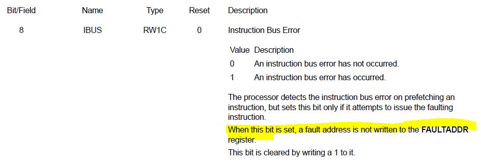
In fault register IBUS bit is set.

I have tried increasing heap and stack memory and giving delays.

Why Instruction bus error is generated?

Regards,

Akshay

  • 8 MHz external crystal used. PLL and divide by 8.

    Controller is working at 25 Mz.

    If I reduce the speed to 10MHz, no fault interrupt is getting generated.

    But my application requires high speed.

    Should I check some other config registers?

    Regards,

    Akshay

  • Hi,
    The IBUSERR is mostly due to the below possible reasons. I can't image running at different frequency can solve the problem. Other than IBUS bit do you see any other bits set? Do you have another chip/board that you can try and can you repeat the same problem?

    a) Branch to invalid memory regions for example caused by incorrect function pointers.
    b) Invalid return due to corrupted stack pointer or stack content.
    c) Incorrect entry in the exception vector table.

    Here is one app note that explains how to debug a software fault situation.
    www.ti.com/.../spma043.pdf
  • Hi Charles,

    I went through the document. The fault address is hold the address of "Debug Core Register Data".
    But the value in that register is 0x00000000.

    NVIC_FAULT_STAT 0x00000100 Configurable Fault Status [Memory Mapped]
    NVIC_HFAULT_STAT 0x40000000 Hard Fault Status [Memory Mapped]
    NVIC_DEBUG_STAT 0x00000000 Debug Status Register [Memory Mapped]
    NVIC_MM_ADDR 0xE000EDF8 Memory Management Fault Address [Memory Mapped]
    NVIC_FAULT_ADDR 0xE000EDF8 Bus Fault Address [Memory Mapped]

    NVIC_DBG_CTRL 0x00030003 Debug Control and Status Reg [Memory Mapped]
    NVIC_DBG_CTRL 0x00030003 Debug Control and Status Reg [Memory Mapped]
    NVIC_DBG_XFER 0x00000000 Debug Core Reg. Transfer Select [Memory Mapped]
    NVIC_DBG_DATA 0x00000000 Debug Core Register Data [Memory Mapped]
    NVIC_DBG_INT 0x01000001 Debug Reset Interrupt Control [Memory Mapped]

    Regards,
    Akshay
  • Hi Akshay,

     When the IBUS bit is set, the fault address is ot written to the FAULTADDR register. In addition, the bit 15 (BFARV) of the NVIC_FAULT_STAT also indicates the FAULTADDR register is not a valid fault address. Therefore, the 0xE000EDF8 is not the source of the fault. 

      You have not answered me if you have tried a different chip or board and can you repeat the same problem? Can you try on the LaunchPad ad can you repeat the same problem

      Can you show how you configure the system clock?

  • Hi Charles,

    I have tried using different board, the problem is repeating.
    But the problem is not seen in launchpad.
    In my hardware I am using 8MHz crystal whereas in launchpad 16MHz crystal is used.

    The configuration I tried on my hardware,

    SysCtlClockSet(SYSCTL_SYSDIV_8 | SYSCTL_USE_PLL | SYSCTL_XTAL_8MHZ |SYSCTL_OSC_MAIN); (25MHz) - Ibus fault
    SysCtlClockSet(SYSCTL_SYSDIV_4 | SYSCTL_USE_PLL | SYSCTL_XTAL_8MHZ |SYSCTL_OSC_MAIN); (50MHz) - Ibus fault
    SysCtlClockSet(SYSCTL_SYSDIV_20 | SYSCTL_USE_PLL | SYSCTL_XTAL_8MHZ |SYSCTL_OSC_MAIN); (10MHz) - No fault observed
    SysCtlClockSet(SYSCTL_SYSDIV_1 | SYSCTL_USE_PLL | SYSCTL_USE_OSC | SYSCTL_OSC_INT); (Internal 16MHz) - No fault observed

    The configuration I tried on launchpad,
    SysCtlClockSet(SYSCTL_SYSDIV_8 | SYSCTL_USE_PLL | SYSCTL_XTAL_16MHZ |SYSCTL_OSC_MAIN); (50MHz) - No fault observed

    Regards,
    Akshay
  • Hi,
    At what point do you get IBUS fault? Right after you configure clock or after you run the code for sometime? If you have run code for sometime and see the fault can you trace the code with breakpoint to find out which line of code caused the ibus fault?

    Can you also try some experiments?

    1. Is it possible for you to change your 8MHz OSC to 16MHz OSC? If the only differencebetween your board and the launchPad is the OSC, then this will be the first thing to investigate?
    2. Your LaunchPad configuration is not 50MHz. It is only 25MHz since the VCO from the PLL is 200MHz and you divide by 8 to become 25Mhz. Can you try to do a divide by 4 in the LaunchPad?
    3. What if you directly drive a single ended 8MHz clock to the OSC0 pin instead of using the crystal?
    4. Do you have the correct external load capacitance on the OSC0 and OSC1 specified by the crystal manufacturer?
  • Hi Akshay,
    I have not heard back from you. I assume you somehow resolved the issue. I will close this thread for now. If you have new questions you can open a new thread or if this issue is not resolved you can reopen this thread.