This thread has been locked.

If you have a related question, please click the "Ask a related question" button in the top right corner. The newly created question will be automatically linked to this question.

TM4C1294KCPDT: GPTM TAOTE trigger, CADC versus PWM0 trigger

Guru 56033 points
Part Number: TM4C1294KCPDT


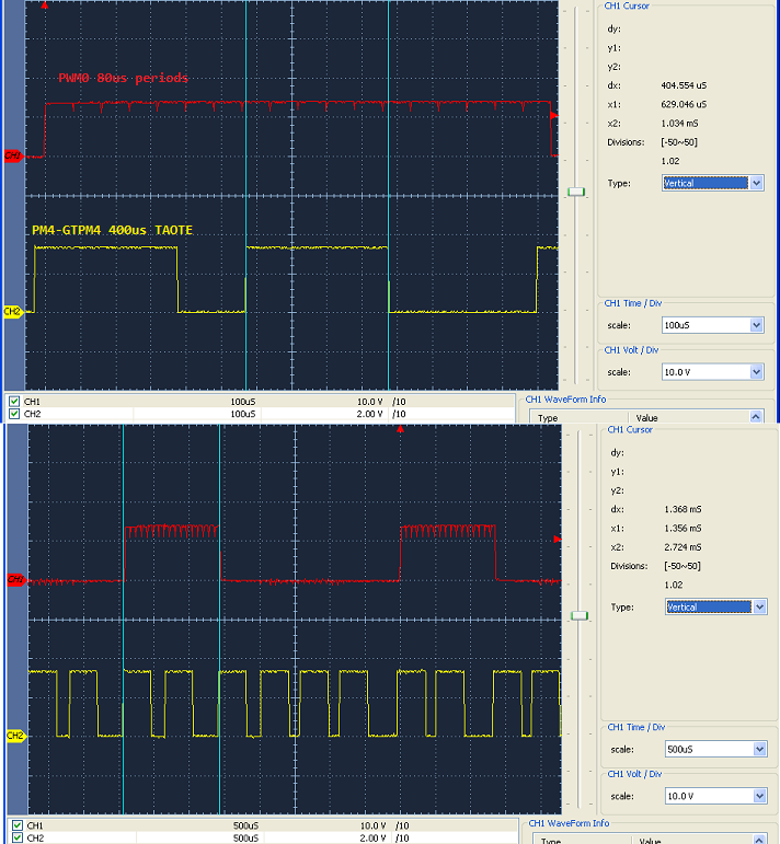
Baffled what should be 400us Oneshot (GPTM4) delay with TAOTE trigger of SS2 ends up being only 9.8us. GPTM4 uses 120mHz SYSCLK loads IALR 0xBB80 (48000 ticks) monitored by GPIO PM3 bit toggles.

Set PM3 high during load of TAILR register then enable Oneshot during every PWM0 output six (80us) periods.  Should delay SS2 trigger for 400us yet oddly GPIO PM3 bit clears during SS2 interrupt handling every 9.8us.  Appears GPTM4 value is being reloaded every 9.8us even though it has not delayed the full count of 48000 ticks it was originally set for.

Why would GPTM4 allow TAILR register reloads prior to it's timeout event when it is configured for Oneshot mode via Tivaware call? Why are 48000 ticks only 9.8us Oneshot events if TAILR is not being reloaded each 80us period when SYSCLK is reported as 120 MHz? Expecting PM3 to stay high 400us but only pulses high roughly 0.1us, lots of ringing in the pulses edges.

Noted: Monitoring PM4 with scope probe, software interrupt was past configured for PM3.

    /* OneShot Timer-4A/B 32 bit triggers ADC0-SS2
     * sample blanking delay INA240 output settling time */
    MAP_TimerClockSourceSet(TIMER4_BASE, TIMER_CLOCK_SYSTEM);
    MAP_TimerConfigure(TIMER4_BASE, TIMER_CFG_ONE_SHOT);
    /* Trigger ADC0 SS2 INA240 samples on GPTM timeout event */
    HWREG(TIMER4_BASE + TIMER_O_ADCEV) |= TIMER_ADCEV_TATOADCEN; 
    /* Set TAOTE bit (GPTMCTL), enable GPTM ADC0 trigger */
    HWREG(TIMER4_BASE + TIMER_O_CTL) |= TIMER_CTL_TAOTE;
    /* Set IMR interrupt disabled for timeout events */
    MAP_TimerIntDisable(TIMER4_BASE, TIMER_TIMA_TIMEOUT);
    /* Enabled after PWMnENABLE register output events */
    MAP_TimerDisable(TIMER4_BASE, TIMER_A);
    /* No interrupt required for PWM triggered event */
    MAP_IntDisable(INT_TIMER4A);

  • BP101,
    I suspect a code issue. We strongly discourage the use of direct register writes as it makes understanding the code more difficult and therefore more prone to error. I suspect you might be overwriting your timer 4 configuration in an interrupt routine.
  • Probe was on PM3 should have been PM4 so GPTM Oneshot is actually working.

  • Hi Bob,

    Perhaps TI engineers can figure out why ADC0 refuses to sample @40us an AINx input level >40mV when PWM0 is the time source of the signal? That is the real issue I have been struggling with for 2 years! It appeared possible by manipulation of variables in EVM stage of development. Sadly the OPAMP sample results were determined inaccurate in the later stages of discovery, today!
  • TAOTE topic relates to the original question further extrapolates the topic through addition of visual aids.

    Redacted thread text~

  • Hi Bob,

    Bob Crosby said:
    We strongly discourage the use of direct register writes as it makes understanding the code more difficult and therefore more prone to error

    Have to disagree as Tivaware calls hide the more obvious registers HWREG quickly reveals inline. Tivaware calls makes it more difficult to use datasheet to trouble shoot issues and fails to document the registers used or even the offsets. Besides earlier versions of Tivaware calls configure of GPTM simply leaves A/B PWM interrupts enabled and was past misconfiguring1/2 wide timers various control register settings. Stack mayhem is another reason to limit repeated rapid function calls to update control registers inside interrupt routines and slows downs instruction execution speed. You can assert an application into hyper space and it can/will still fail if the POP/PUSH becomes excessive upon RAM. Note TI-RTOS encourages disabling of Tivaware asserts for good reason, they are mostly there for debug purposes.