This thread has been locked.

If you have a related question, please click the "Ask a related question" button in the top right corner. The newly created question will be automatically linked to this question.

CCS/TM4C1294NCPDT: TM4C1294NCPDT

Part Number: TM4C1294NCPDT
Other Parts Discussed in Thread: EK-TM4C1294XL

Tool/software: Code Composer Studio

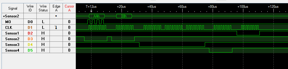
I have a TM4C129 which has sensors that I am trying to read from. I cannot read any other pins than the ones I used below in the code. In the code below, I am keep reading from temp. sensor. I do not need to write anything to MOSI. All I am trying to do is clocking and reading from the sensor.
But I cannot get the reading for some reason. Not sure what I am missing in the code. I have checked other examples (ti_master.c etc) There is nothing different than my code. Any idea what am I missing?
Thanks.

 uint32_t ui32SysClock = SysCtlClockFreqSet((SYSCTL_XTAL_25MHZ |
                                       SYSCTL_OSC_MAIN |
                                       SYSCTL_USE_OSC), 25000000);


void init_sensor(void)
{
    SysCtlPeripheralEnable(SYSCTL_PERIPH_SSI0);
    while (!SysCtlPeripheralReady(SYSCTL_PERIPH_SSI0))
        ;
    SysCtlPeripheralEnable(SYSCTL_PERIPH_GPIOA);
    while (!SysCtlPeripheralReady(SYSCTL_PERIPH_GPIOA))
        ;

    SysCtlPeripheralEnable(SYSCTL_PERIPH_GPIOH);
    while (!SysCtlPeripheralReady(SYSCTL_PERIPH_GPIOH))
        ;
    GPIOPinTypeGPIOOutput(GPIO_PORTH_BASE, GPIO_PIN_0);  // CS as output
    GPIOPinTypeGPIOOutput(GPIO_PORTA_BASE, GPIO_PIN_2);  // CLK as output
    GPIOPinTypeGPIOInput(GPIO_PORTA_BASE, GPIO_PIN_5);  // MISO as output
    GPIOPinConfigure(GPIO_PA2_SSI0CLK); //CLK
    GPIOPinConfigure(GPIO_PA5_SSI0XDAT1);  //MISO
    GPIOPinTypeSSI(GPIO_PORTA_BASE,
    GPIO_PIN_5 | GPIO_PIN_2);
    SSIConfigSetExpClk(SSI0_BASE, ui32SysClock, SSI_FRF_MOTO_MODE_3,
    SSI_MODE_MASTER,
                       1000000, 8);
    SSIEnable(SSI0_BASE);
}


void read_sensor(void){
	 while (SSIBusy(SSI0_BASE))
        ;
    SSIDataGet(SSI0_BASE, &dataRx[0]);

}


int main(void)
{
	while(1){
		read_sensor();	
	}
}

  • On an SPI every transaction is both a write and a read. A write started by the master generates the clocks that both write to the slave and read from the slave. At the same time the slave reads from the master and writes to the master. Sometimes, you only need one operation, write or read. In that case the other data is dummy data and can be ignored.

    To read from a slave device the TM4C must call SSIDataPut(). You can supply dummy data. That initiates the transaction and data clocked out of the slave will be stored in the FIFO. Then a call to SSIDataGet() will read the data from the FIFO.
  • Bob,

    Thanks for the clarification. Please see code below. I still cannot read data from SPI bus. When I debug. I do not see any data in the ulDataRx. Am I missing something?

    Thanks.

    #define NUM_SSI_DATA            8
    
    uint32_t pui32DataTx[NUM_SSI_DATA];
    uint32_t pui32DataRx[NUM_SSI_DATA];
    uint32_t ui32SysClock;
    
    const unsigned char ulDataTx[NUM_SSI_DATA] = { 0x88, 0xF8, 0xF8, 0x88, 0x01,
                                                   0x1F, 0x1F, 0x01 };
    											   
    uint32_t ulDataRx[NUM_SSI_DATA] = { 0 };
    
    // Bit-wise reverses a number.
    unsigned char Reverse(unsigned char ucNumber)
    {
        unsigned short ucIndex;
        unsigned short ucReversedNumber = 0;
        for (ucIndex = 0; ucIndex < 8; ucIndex++)
        {
            ucReversedNumber = ucReversedNumber << 1;
            ucReversedNumber |= ((1 << ucIndex) & ucNumber) >> ucIndex;
        }
        return ucReversedNumber;
    }
    
    
    int main(void){
    	 ui32SysClock = SysCtlClockFreqSet((SYSCTL_XTAL_25MHZ | SYSCTL_OSC_MAIN |
        SYSCTL_USE_PLL | SYSCTL_CFG_VCO_480),
                                            120000000);
    
    
    	unsigned long ulindex;
        unsigned long ulData;
    	
    	 SysCtlPeripheralEnable(SYSCTL_PERIPH_SSI2);
        SysCtlPeripheralEnable(SYSCTL_PERIPH_GPIOD);
    
        GPIOPinConfigure(GPIO_PD3_SSI2CLK);
        GPIOPinConfigure(GPIO_PD2_SSI2FSS);
        GPIOPinConfigure(GPIO_PD1_SSI2XDAT0);
        GPIOPinConfigure(GPIO_PD0_SSI2XDAT1);
        GPIOPinTypeSSI(GPIO_PORTD_BASE,
        GPIO_PIN_3 | GPIO_PIN_2 | GPIO_PIN_1 | GPIO_PIN_0);
        SSIConfigSetExpClk(SSI2_BASE, ui32SysClock, SSI_FRF_MOTO_MODE_0,
        SSI_MODE_MASTER,
                           10000, 16);
        SSIEnable(SSI2_BASE);
    
        while (1)
        {
            for (ulindex = 0; ulindex < NUM_SSI_DATA; ulindex++)
            {
                ulData = (Reverse(ulDataTx[ulindex]) << 8) + (1 << ulindex);
                SSIDataPut(SSI2_BASE, ulData);
            }
            while (SSIBusy(SSI2_BASE))
            {
            }
            for (ulindex = 0; ulindex < NUM_SSI_DATA; ulindex++)
            {
                SSIDataGet(SSI2_BASE, &ulDataRx[ulindex]);
            }
        }	
    }

  • Did you check the signal on PD0 (SSI2Tx) with a scope or logic analyzer? Do you have PD0 connected to PD1 (SSI2Rx)?

    Here is an example project that can be run on an EK-TM4c1294XL Launchpad. It uses SSI0. To see the data received being echoed back, connect PA4 to PA5 with a jumper wire. Use Code Composer Studio "File" -> "Import" to import this project into your workspace.

    /cfs-file/__key/communityserver-discussions-components-files/908/5808.SPI_5F00_Master.zip

  • Thank you for the response. I was able to make it work with your post above. Now, I have to change the specifications. I have to use GPIO_PORTA_BASE. I have 4 slaves and I must use CS/SS lines PORTH's 0,1,2,3 pins. Please see the code below. I could not make SYSCTL_PERIPH_GPIOH, GPIO_PIN_0 work. I cannot send any data it blocks at the SSIDataPut(SSI0_BASE, pui32DataTx[ui32Index]);. I am not sure what I am doing wrong. Also in order to change the SS/CS where do I need to put the pin low and high?
    Best,

        SysCtlPeripheralEnable(SYSCTL_PERIPH_GPIOA);
        while (!SysCtlPeripheralReady(SYSCTL_PERIPH_GPIOA))
            ;
        SysCtlPeripheralEnable(SYSCTL_PERIPH_GPIOH);
        while (!SysCtlPeripheralReady(SYSCTL_PERIPH_GPIOH))
            ;
    
        SysCtlPeripheralEnable(SYSCTL_PERIPH_SSI0);
        while (!SysCtlPeripheralReady(SYSCTL_PERIPH_SSI0))
            ;
    
        GPIOPinTypeGPIOOutput(SYSCTL_PERIPH_GPIOH, GPIO_PIN_0); // CS as output
        GPIOPinTypeGPIOInput(GPIO_PORTA_BASE, GPIO_PIN_5);      // MISO as input
        GPIOPinTypeGPIOOutput(GPIO_PORTA_BASE, GPIO_PIN_4);     // MOSI as input
        GPIOPinTypeGPIOOutput(GPIO_PORTA_BASE, GPIO_PIN_2);    // CLK as output
    
        GPIOPinTypeSSI(GPIO_PORTA_BASE,
        GPIO_PIN_5 | GPIO_PIN_4 | GPIO_PIN_3 | GPIO_PIN_2);
    	
    	SSIDisable(SSI0_BASE);
        SSIConfigSetExpClk(SSI0_BASE, ui32SysClock, SSI_FRF_MOTO_MODE_3,
        SSI_MODE_MASTER,
                           1000000, 8);
        SSIEnable(SSI0_BASE);
    
        while (SSIDataGetNonBlocking(SSI0_BASE, &pui32DataRx[0]))
        {
        }
    
        //
        // Initialize the data to send.
        //
        pui32DataTx[0] = 1;
        pui32DataTx[1] = 2;
        pui32DataTx[2] = 3;
    
        //
        // Send 3 bytes of data.
        //
        GPIOPinWrite(GPIO_PORTH_BASE, GPIO_PIN_0, 0x0);
        for (ui32Index = 0; ui32Index < NUM_SSI_DATA; ui32Index++)
        {
            //
            // Send the data using the "blocking" put function.  This function
            // will wait until there is room in the send FIFO before returning.
            // This allows you to assure that all the data you send makes it into
            // the send FIFO.s
            //
            SSIDataPut(SSI0_BASE, pui32DataTx[ui32Index]);
        }
    
        while (SSIBusy(SSI0_BASE))
        {
        }
    
        for (ui32Index = 0; ui32Index < NUM_SSI_DATA; ui32Index++)
        {
            SSIDataGet(SSI0_BASE, &pui32DataRx[ui32Index]);
    
                   pui32DataRx[ui32Index] &= 0x00FF;
        }
    

  • Are you trying to do something like this?

     The code looks like this:

    #include <stdbool.h>
    #include <stdint.h>
    #include "inc/hw_memmap.h"
    #include "inc/hw_types.h"
    #include "inc/hw_ssi.h"
    #include "driverlib/gpio.h"
    #include "driverlib/pin_map.h"
    #include "driverlib/ssi.h"
    #include "driverlib/sysctl.h"
    #include "driverlib/uart.h"
    #include "utils/uartstdio.h"
    
    //*****************************************************************************
    //
    //! \addtogroup ssi_examples_list
    //! <h1>SPI Master (spi_master)</h1>
    //!
    //! This example shows how to configure the SSI0 as SPI Master.  The code will
    //! send three characters on the master Tx then polls the receive FIFO until
    //! 3 characters are received on the master Rx.
    //!
    //! This example uses the following peripherals and I/O signals.  You must
    //! review these and change as needed for your own board:
    //! - SSI0 peripheral
    //! - GPIO Port A peripheral (for SSI0 pins)
    //! - SSI0Clk - PA2
    //! - SSI0Fss - PA3
    //! - SSI0Rx  - PA4
    //! - SSI0Tx  - PA5
    //!
    //! This example uses the following interrupt handlers.  To use this example
    //! in your own application you must add these interrupt handlers to your
    //! vector table.
    //! - None.
    //
    //*****************************************************************************
    
    //*****************************************************************************
    //
    // Number of bytes to send and receive.
    //
    //*****************************************************************************
    #define NUM_SSI_DATA        4
    #define SENSOR1             GPIO_PIN_0
    #define SENSOR2             GPIO_PIN_1
    #define SENSOR3             GPIO_PIN_2
    #define SENSOR4             GPIO_PIN_3
    
    unsigned int writeReadSensor(unsigned int sensor, unsigned int size,  unsigned int *buffer);
    
    //*****************************************************************************
    //
    // Configure SSI0 in master Freescale (SPI) mode.  This example will send out
    // 3 bytes of data, then wait for 3 bytes of data to come in.  This will all be
    // done using the polling method.
    //
    //*****************************************************************************
    int
    main(void)
    {
        uint32_t ui32SysClock;
    
        uint32_t pui32DataSensor1[NUM_SSI_DATA];
        uint32_t pui32DataSensor2[NUM_SSI_DATA];
        uint32_t pui32DataSensor3[NUM_SSI_DATA];
        uint32_t pui32DataSensor4[NUM_SSI_DATA];
    
        ui32SysClock = SysCtlClockFreqSet((SYSCTL_XTAL_25MHZ |
                                           SYSCTL_OSC_MAIN |
                                           SYSCTL_USE_OSC), 25000000);
    
        //
        // The SSI0 peripheral must be enabled for use.
        //
        SysCtlPeripheralEnable(SYSCTL_PERIPH_SSI0);
    
        //
        // For this example SSI0 is used with PortA[5:2].  The actual port and pins
        // used may be different on your part, consult the data sheet for more
        // information.  GPIO port A needs to be enabled so these pins can be used.
        // TODO: change this to whichever GPIO port you are using.
        //
        SysCtlPeripheralEnable(SYSCTL_PERIPH_GPIOA);
        // Use GPIOH pins for manual chip selects
        SysCtlPeripheralEnable(SYSCTL_PERIPH_GPIOH);
    
        //
        // Configure the pin muxing for SSI0 functions on port A2, A3, A4, and A5.
        // This step is not necessary if your part does not support pin muxing.
        // TODO: change this to select the port/pin you are using.
        //
        GPIOPinConfigure(GPIO_PA2_SSI0CLK);
        GPIOPinConfigure(GPIO_PA4_SSI0XDAT0); // TX
        GPIOPinConfigure(GPIO_PA5_SSI0XDAT1); // RX
    
        //
        // Configure the GPIO settings for the SSI pins.  This function also gives
        // control of these pins to the SSI hardware.  Consult the data sheet to
        // see which functions are allocated per pin.
        // The pins are assigned as follows:
        //      PA5 - SSI0Rx
        //      PA4 - SSI0Tx
        //      PA2 - SSI0CLK
        // TODO: change this to select the port/pin you are using.
        //
        GPIOPinTypeSSI(GPIO_PORTA_BASE, GPIO_PIN_5 | GPIO_PIN_4 | GPIO_PIN_2);
        GPIOPinTypeGPIOOutput(GPIO_PORTH_BASE, SENSOR1 | SENSOR2 | SENSOR3 | SENSOR4);
        // Start with all chip selects high (inactive)
        GPIOPinWrite(GPIO_PORTH_BASE, (SENSOR1 | SENSOR2 | SENSOR3 | SENSOR4),  0x0F);
    
    
        //
        // Configure and enable the SSI port for SPI master mode.  Use SSI0,
        // system clock supply, idle clock level low and active low clock in
        // freescale SPI mode, master mode, 1MHz SSI frequency, and 8-bit data.
        // For SPI mode, you can set the polarity of the SSI clock when the SSI
        // unit is idle.  You can also configure what clock edge you want to
        // capture data on.  Please reference the datasheet for more information on
        // the different SPI modes.
        //
        SSIConfigSetExpClk(SSI0_BASE, ui32SysClock, SSI_FRF_MOTO_MODE_0,
                           SSI_MODE_MASTER, 1000000, 8);
    
        //
        // Enable the SSI0 module.
        //
        SSIEnable(SSI0_BASE);
        //
        // Read any residual data from the SSI port.  This makes sure the receive
        // FIFOs are empty, so we don't read any unwanted junk.  This is done here
        // because the SPI SSI mode is full-duplex, which allows you to send and
        // receive at the same time.  The SSIDataGetNonBlocking function returns
        // "true" when data was returned, and "false" when no data was returned.
        // The "non-blocking" function checks if there is any data in the receive
        // FIFO and does not "hang" if there isn't.
        //
        while(SSIDataGetNonBlocking(SSI0_BASE, &pui32DataSensor1[0]))
        {
        }
    
        // send a 0xAA to sensor 2
        pui32DataSensor2[0] = 0xAA;
        writeReadSensor(SENSOR2, 1, pui32DataSensor2);
        // read a byte from sensor 2
        writeReadSensor(SENSOR2, 1, pui32DataSensor2);
    
        // read 3 bytes from sensor 3
        writeReadSensor(SENSOR3, 3, pui32DataSensor3);
    
        // read 1 bytes from sensor 4
        writeReadSensor(SENSOR4, 1, pui32DataSensor4);
    
        // read 1 bytes from sensor 1
        writeReadSensor(SENSOR1, 1, pui32DataSensor1);
    
        // Return no errors
        //
        return(0);
    }
    
    unsigned int writeReadSensor(unsigned int sensor, unsigned int size,  unsigned int *buffer)
    {
        unsigned int i;
    
        if(size > NUM_SSI_DATA)
        {
            size = NUM_SSI_DATA;
        }
        GPIOPinWrite(GPIO_PORTH_BASE, sensor,  0); // Chip select goes low
        for(i = 0; i < size; i++)
        {
            SSIDataPut(SSI0_BASE, buffer[i]); // send from the buffer
            SSIDataGet(SSI0_BASE, &buffer[i]); // read into the buffer
        }
        GPIOPinWrite(GPIO_PORTH_BASE, sensor,  sensor); // Chip select goes high
        return size; // return number of bytes sent and received
    }
    

    The project is also attached:

    /cfs-file/__key/communityserver-discussions-components-files/908/SPI0_5F00_ManualCS.zip

  • Hi Bob,

    Yes,  my purpose is similar to what you posted above. It helped a lot. Is it possible to read only 12 bits, and mask it at once. How can I read 12 bits ? Can I do this ?

    SSIConfigSetExpClk(SSI0_BASE, ui32SysClock, SSI_FRF_MOTO_MODE_0, SSI_MODE_MASTER, 1000000, 12);

    Also, in the data sheet it says "

    For master legacy mode,
    the SYSCLK or ALTCLK must be at least two times faster than the SSInClk, with the
    restriction that SSInClk cannot be faster than 60 MHz."  if I want to use 120Mhz clock as shown below how do I need to set up the SSInClk? Thank you

    ui32SysClock = SysCtlClockFreqSet(
                (SYSCTL_XTAL_25MHZ | SYSCTL_OSC_MAIN |
                SYSCTL_USE_PLL | SYSCTL_CFG_VCO_480),
                120000000);

  • Yes, if you need to transmit and receive 12 bits at a time, change the last parameter in SSIConfigExpClk() to 12 like you showed. To change SSInClk, the transmission frequency, change the second to last parameter. In my example I was using 1M baud (1000000). You can go up to 60M baud, but make sure the slave and the physical circuit can handle that high speed.