This thread has been locked.

If you have a related question, please click the "Ask a related question" button in the top right corner. The newly created question will be automatically linked to this question.

TM4C1294NCPDT: CAN bus transmission not sending (Object interrupt flag not raised)

Part Number: TM4C1294NCPDT
Other Parts Discussed in Thread: SN65HVD1050,

Hello,

I am using SN65HVD1050 to work with the CANbus on TM4C1294NCPDT.

Here is my code on the Tiva

volatile uint32_t g_ui32IntCount = 0;

// Counter that are used to count the number of message on each of the three message that are used.
volatile uint32_t g_ui32Msg1Count = 0;
volatile uint32_t g_ui32Msg2Count = 0;
volatile uint32_t g_ui32Msg3Count = 0;

// Flag to indicate message Object 3 has sent a message
volatile bool g_bMsgObj3Sent = 0;

// Flag to indicate transmission error has occured
volatile bool g_bErrFlag = 0;

// Can object that hold the separate CAN message
tCANMsgObject g_sCANMsgObject1;
tCANMsgObject g_sCANMsgObject2;
tCANMsgObject g_sCANMsgObject3;

// Message buffer that hold the contents of the 4 differenet message that are being transmitted.
uint8_t g_pui8Msg1[4] = { 0, 0, 0, 0 };
uint8_t g_pui8Msg2[5] = { 2, 2, 2, 2, 2 };
uint8_t g_pui8Msg3[6] = { 3, 3, 3, 3, 3, 3 };
uint8_t g_pui8Msg4[8] = { 4, 4, 4, 4, 5, 5, 5, 5 };


void init_canbustest(uint32_t sysClock) {

    SysCtlPeripheralEnable(SYSCTL_PERIPH_GPIOB);
    GPIOPinConfigure(GPIO_PB0_CAN1RX);
    GPIOPinConfigure(GPIO_PB1_CAN1TX);
    GPIOPinTypeCAN(GPIO_PORTB_BASE, GPIO_PIN_0 | GPIO_PIN_1);

    /* Enable CAN Peripheral */
    SysCtlPeripheralDisable(SYSCTL_PERIPH_CAN1);
    SysCtlPeripheralReset(SYSCTL_PERIPH_CAN1);
    SysCtlPeripheralEnable(SYSCTL_PERIPH_CAN1);


    /* Initialize CAN controller */
    CANInit(CAN1_BASE);

    /* Setup CAN Controller */
    CANBitRateSet(CAN1_BASE, sysClock, 500000);

    /* Enable Interrupt of CAN peripheral */
    //    CANIntRegister(CAN1_BASE, CAN_irq);
    CANIntEnable(CAN1_BASE, CAN_INT_MASTER | CAN_INT_ERROR | CAN_INT_STATUS);


    IntEnable(INT_CAN1);
    CANEnable(CAN1_BASE);

    g_sCANMsgObject1.ui32MsgID = 0x1001;
    g_sCANMsgObject1.ui32MsgIDMask = 0;
    g_sCANMsgObject1.ui32Flags = MSG_OBJ_TX_INT_ENABLE;
    g_sCANMsgObject1.ui32MsgLen = sizeof(g_pui8Msg1);
    g_sCANMsgObject1.pui8MsgData = g_pui8Msg1;

    g_sCANMsgObject2.ui32MsgID = 0x2001;
    g_sCANMsgObject2.ui32MsgIDMask = 0;
    g_sCANMsgObject2.ui32Flags = MSG_OBJ_TX_INT_ENABLE;
    g_sCANMsgObject2.ui32MsgLen = sizeof(g_pui8Msg2);
    g_sCANMsgObject2.pui8MsgData = g_pui8Msg2;

}

void CAN1IntHandler() {
    uint32_t ui32Status;

    ui32Status = CANIntStatus(CAN1_BASE, CAN_INT_STS_CAUSE);
    UARTprintf("[CAN1IntHandler]2ndCause: %x\n", ui32Status);

    if(ui32Status == CAN_INT_INTID_STATUS) {
        ui32Status = CANStatusGet(CAN1_BASE, CAN_STS_CONTROL);
        UARTprintf("[CAN_INT_INTID_STATUS]Status: %x\n", ui32Status);

        g_bErrFlag = 1;
    } else if(ui32Status == 1) {
        CANIntClear(CAN1_BASE, 1);
        UARTprintf("[MsgObj1]Status: %x\n", ui32Status);

        g_ui32Msg1Count++;
        g_bErrFlag = 0;
    } else if(ui32Status == 2) {
        CANIntClear(CAN1_BASE, 2);
        UARTprintf("[MsgObj2]Status: %x\n", ui32Status);

        g_ui32Msg2Count++;
        g_bErrFlag = 0;
    } else {
        UARTprintf("Nothing should be printed\n");
    }
}

void send_can_msg_test() {
    PrintCANMessageInfo(&g_sCANMsgObject1, 1);
    CANMessageSet(CAN1_BASE, 1, &g_sCANMsgObject1, MSG_OBJ_TYPE_TX);

    if(g_bErrFlag) UARTprintf("Bus Error\n");

}

void PrintCANMessageInfo(tCANMsgObject *psCANMsg, uint32_t ui32MsgObj)
{
    unsigned int uIdx;

    UARTprintf("Sending msg: obj=%d ID=0x%04X msg=0x", ui32MsgObj,
               psCANMsg->ui32MsgID);
    for(uIdx = 0; uIdx < psCANMsg->ui32MsgLen; uIdx++)
    {
        UARTprintf("%02X ", psCANMsg->pui8MsgData[uIdx]);
    }
    UARTprintf("\n");
}

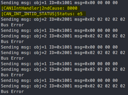
Here is a snippet of my Serial COM port.

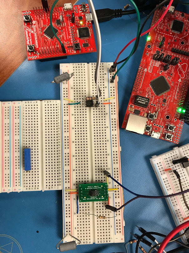
Here is the picture of my setup (I am using one SN65HVD1050 and one MCP2551)


From the COM port, I can see that the interrupt never happen when the message Object 1 is sent. So it results in BUS Error.

How should I fix this issue of my CAN bus?

Thanks,

Alex

  • The '5' of the status 0xE5 is indicating a bit '0' error. That means the TM4C CANTX pin was driving a 0 (dominate), but the CANRX pin still saw a high (recessive). This implies that there is an issue with your hookup to the either the CAN transceiver or the bus itself. Using an oscilloscope or logic analyzer compare the CANTX pin to the state of the CAN bus.
  • Hello Bob,

    Thanks for a quick response. There are a few progression, however, I have some concerns that still need to clear up.

    Below are the changes from last post

    1. I used another TM4C129 instead of TM4C123 with the simple RX code. 

    Code on the receiver side 

    //*****************************************************************************
    //
    // simple_rx.c - Example demonstrating simple CAN message reception.
    //
    // Copyright (c) 2010-2017 Texas Instruments Incorporated.  All rights reserved.
    // Software License Agreement
    //
    //   Redistribution and use in source and binary forms, with or without
    //   modification, are permitted provided that the following conditions
    //   are met:
    //
    //   Redistributions of source code must retain the above copyright
    //   notice, this list of conditions and the following disclaimer.
    //
    //   Redistributions in binary form must reproduce the above copyright
    //   notice, this list of conditions and the following disclaimer in the
    //   documentation and/or other materials provided with the
    //   distribution.
    //
    //   Neither the name of Texas Instruments Incorporated nor the names of
    //   its contributors may be used to endorse or promote products derived
    //   from this software without specific prior written permission.
    //
    // THIS SOFTWARE IS PROVIDED BY THE COPYRIGHT HOLDERS AND CONTRIBUTORS
    // "AS IS" AND ANY EXPRESS OR IMPLIED WARRANTIES, INCLUDING, BUT NOT
    // LIMITED TO, THE IMPLIED WARRANTIES OF MERCHANTABILITY AND FITNESS FOR
    // A PARTICULAR PURPOSE ARE DISCLAIMED. IN NO EVENT SHALL THE COPYRIGHT
    // OWNER OR CONTRIBUTORS BE LIABLE FOR ANY DIRECT, INDIRECT, INCIDENTAL,
    // SPECIAL, EXEMPLARY, OR CONSEQUENTIAL DAMAGES (INCLUDING, BUT NOT
    // LIMITED TO, PROCUREMENT OF SUBSTITUTE GOODS OR SERVICES; LOSS OF USE,
    // DATA, OR PROFITS; OR BUSINESS INTERRUPTION) HOWEVER CAUSED AND ON ANY
    // THEORY OF LIABILITY, WHETHER IN CONTRACT, STRICT LIABILITY, OR TORT
    // (INCLUDING NEGLIGENCE OR OTHERWISE) ARISING IN ANY WAY OUT OF THE USE
    // OF THIS SOFTWARE, EVEN IF ADVISED OF THE POSSIBILITY OF SUCH DAMAGE.
    //
    // This is part of revision 2.1.4.178 of the Tiva Firmware Development Package.
    //
    //*****************************************************************************
    
    #include <stdbool.h>
    #include <stdint.h>
    #include "inc/hw_can.h"
    #include "inc/hw_ints.h"
    #include "inc/hw_memmap.h"
    #include "inc/hw_types.h"
    #include "driverlib/can.h"
    #include "driverlib/gpio.h"
    #include "driverlib/interrupt.h"
    #include "driverlib/pin_map.h"
    #include "driverlib/sysctl.h"
    #include "driverlib/uart.h"
    #include "utils/uartstdio.h"
    
    //*****************************************************************************
    //
    //! \addtogroup can_examples_list
    //! <h1>Simple CAN RX (simple_rx)</h1>
    //!
    //! This example shows the basic setup of CAN in order to receive messages
    //! from the CAN bus.  The CAN peripheral is configured to receive messages
    //! with any CAN ID and then print the message contents to the console.
    //!
    //! This example uses the following peripherals and I/O signals.  You must
    //! review these and change as needed for your own board:
    //! - CAN0 peripheral
    //! - GPIO port B peripheral (for CAN0 pins)
    //! - CAN0RX - PB4
    //! - CAN0TX - PB5
    //!
    //! The following UART signals are configured only for displaying console
    //! messages for this example.  These are not required for operation of CAN.
    //! - GPIO port A peripheral (for UART0 pins)
    //! - UART0RX - PA0
    //! - UART0TX - PA1
    //!
    //! This example uses the following interrupt handlers.  To use this example
    //! in your own application you must add these interrupt handlers to your
    //! vector table.
    //! - INT_CAN0 - CANIntHandler
    //
    //*****************************************************************************
    
    //*****************************************************************************
    //
    // A counter that keeps track of the number of times the RX interrupt has
    // occurred, which should match the number of messages that were received.
    //
    //*****************************************************************************
    volatile uint32_t g_ui32MsgCount = 0;
    
    //*****************************************************************************
    //
    // A flag for the interrupt handler to indicate that a message was received.
    //
    //*****************************************************************************
    volatile bool g_bRXFlag = 0;
    
    //*****************************************************************************
    //
    // A flag to indicate that some reception error occurred.
    //
    //*****************************************************************************
    volatile bool g_bErrFlag = 0;
    
    //*****************************************************************************
    //
    // This function sets up UART0 to be used for a console to display information
    // as the example is running.
    //
    //*****************************************************************************
    void
    InitConsole(void)
    {
        //
        // Enable GPIO port A which is used for UART0 pins.
        // TODO: change this to whichever GPIO port you are using.
        //
        SysCtlPeripheralEnable(SYSCTL_PERIPH_GPIOA);
    
        //
        // Configure the pin muxing for UART0 functions on port A0 and A1.
        // This step is not necessary if your part does not support pin muxing.
        // TODO: change this to select the port/pin you are using.
        //
        GPIOPinConfigure(GPIO_PA0_U0RX);
        GPIOPinConfigure(GPIO_PA1_U0TX);
    
        //
        // Enable UART0 so that we can configure the clock.
        //
        SysCtlPeripheralEnable(SYSCTL_PERIPH_UART0);
    
        //
        // Use the internal 16MHz oscillator as the UART clock source.
        //
        UARTClockSourceSet(UART0_BASE, UART_CLOCK_PIOSC);
    
        //
        // Select the alternate (UART) function for these pins.
        // TODO: change this to select the port/pin you are using.
        //
        GPIOPinTypeUART(GPIO_PORTA_BASE, GPIO_PIN_0 | GPIO_PIN_1);
    
        //
        // Initialize the UART for console I/O.
        //
        UARTStdioConfig(0, 115200, 16000000);
    }
    
    //*****************************************************************************
    //
    // This function is the interrupt handler for the CAN peripheral.  It checks
    // for the cause of the interrupt, and maintains a count of all messages that
    // have been received.
    //
    //*****************************************************************************
    void
    CANIntHandler(void)
    {
        uint32_t ui32Status;
    
        //
        // Read the CAN interrupt status to find the cause of the interrupt
        //
        ui32Status = CANIntStatus(CAN1_BASE, CAN_INT_STS_CAUSE);
        UARTprintf("[CAN1IntHandler]Cause: %x\n", ui32Status);
        //
        // If the cause is a controller status interrupt, then get the status
        //
        if(ui32Status == CAN_INT_INTID_STATUS)
        {
            //
            // Read the controller status.  This will return a field of status
            // error bits that can indicate various errors.  Error processing
            // is not done in this example for simplicity.  Refer to the
            // API documentation for details about the error status bits.
            // The act of reading this status will clear the interrupt.
            //
            ui32Status = CANStatusGet(CAN1_BASE, CAN_STS_CONTROL);
            UARTprintf("[INT STATUS]: %x\n", ui32Status);
            //
            // Set a flag to indicate some errors may have occurred.
            //
            g_bErrFlag = 1;
        }
    
        //
        // Check if the cause is message object 1, which what we are using for
        // receiving messages.
        //
        else if(ui32Status == 1)
        {
            //
            // Getting to this point means that the RX interrupt occurred on
            // message object 1, and the message reception is complete.  Clear the
            // message object interrupt.
            //
            CANIntClear(CAN1_BASE, 1);
            UARTprintf("[MsgRecevied Interrupt]: %x\n", ui32Status);
            //
            // Increment a counter to keep track of how many messages have been
            // received.  In a real application this could be used to set flags to
            // indicate when a message is received.
            //
            g_ui32MsgCount++;
    
            //
            // Set flag to indicate received message is pending.
            //
            g_bRXFlag = 1;
    
            //
            // Since a message was received, clear any error flags.
            //
            g_bErrFlag = 0;
        }
    
        //
        // Otherwise, something unexpected caused the interrupt.  This should
        // never happen.
        //
        else
        {
            //
            // Spurious interrupt handling can go here.
            //
        }
    }
    
    //*****************************************************************************
    //
    // Configure the CAN and enter a loop to receive CAN messages.
    //
    //*****************************************************************************
    int
    main(void)
    {
    
        uint32_t ui32SysClock;
        tCANMsgObject sCANMessage;
        uint8_t pui8MsgData[8];
    
        //
        // Set the clocking to run directly from the external crystal/oscillator.
        // TODO: The SYSCTL_XTAL_ value must be changed to match the value of the
        // crystal used on your board.
        //
        ui32SysClock = SysCtlClockFreqSet((SYSCTL_XTAL_25MHZ | SYSCTL_OSC_MAIN | SYSCTL_USE_PLL | SYSCTL_CFG_VCO_480), 120000000);    //
        // Set up the serial console to use for displaying messages.  This is
        // just for this example program and is not needed for CAN operation.
        //
        InitConsole();
    
        //
        // For this example CAN0 is used with RX and TX pins on port B4 and B5.
        // The actual port and pins used may be different on your part, consult
        // the data sheet for more information.
        // GPIO port B needs to be enabled so these pins can be used.
        // TODO: change this to whichever GPIO port you are using
        //
        SysCtlPeripheralEnable(SYSCTL_PERIPH_GPIOB);
    
        //
        // Configure the GPIO pin muxing to select CAN0 functions for these pins.
        // This step selects which alternate function is available for these pins.
        // This is necessary if your part supports GPIO pin function muxing.
        // Consult the data sheet to see which functions are allocated per pin.
        // TODO: change this to select the port/pin you are using
        //
        GPIOPinConfigure(GPIO_PB0_CAN1RX);
        GPIOPinConfigure(GPIO_PB1_CAN1TX);
    
        //
        // Enable the alternate function on the GPIO pins.  The above step selects
        // which alternate function is available.  This step actually enables the
        // alternate function instead of GPIO for these pins.
        // TODO: change this to match the port/pin you are using
        //
        GPIOPinTypeCAN(GPIO_PORTB_BASE, GPIO_PIN_0 | GPIO_PIN_1);
    
        //
        // The GPIO port and pins have been set up for CAN.  The CAN peripheral
        // must be enabled.
        //
        SysCtlPeripheralEnable(SYSCTL_PERIPH_CAN1);
    
        //
        // Initialize the CAN controller
        //
        CANInit(CAN1_BASE);
    
        //
        // Set up the bit rate for the CAN bus.  This function sets up the CAN
        // bus timing for a nominal configuration.  You can achieve more control
        // over the CAN bus timing by using the function CANBitTimingSet() instead
        // of this one, if needed.
        // In this example, the CAN bus is set to 500 kHz.  In the function below,
        // the call to SysCtlClockGet() or ui32SysClock is used to determine the
        // clock rate that is used for clocking the CAN peripheral.  This can be
        // replaced with a  fixed value if you know the value of the system clock,
        // saving the extra function call.  For some parts, the CAN peripheral is
        // clocked by a fixed 8 MHz regardless of the system clock in which case
        // the call to SysCtlClockGet() or ui32SysClock should be replaced with
        // 8000000.  Consult the data sheet for more information about CAN
        // peripheral clocking.
        //
    #if defined(TARGET_IS_TM4C129_RA0) ||                                         \
            defined(TARGET_IS_TM4C129_RA1) ||                                         \
            defined(TARGET_IS_TM4C129_RA2)
        CANBitRateSet(CAN1_BASE, ui32SysClock, 500000);
    #else
        CANBitRateSet(CAN1_BASE, SysCtlClockGet(), 500000);
    #endif
    
        //
        // Enable interrupts on the CAN peripheral.  This example uses static
        // allocation of interrupt handlers which means the name of the handler
        // is in the vector table of startup code.  If you want to use dynamic
        // allocation of the vector table, then you must also call CANIntRegister()
        // here.
        //
    
        //
        CANIntRegister(CAN1_BASE, CANIntHandler); // if using dynamic vectors
        CANIntEnable(CAN1_BASE, CAN_INT_MASTER | CAN_INT_ERROR | CAN_INT_STATUS);
    
        //
        // Enable the CAN interrupt on the processor (NVIC).
        //
        IntEnable(INT_CAN0);
    
        //
        // Enable the CAN for operation.
        //
        CANEnable(CAN1_BASE);
    
        //
        // Initialize a message object to be used for receiving CAN messages with
        // any CAN ID.  In order to receive any CAN ID, the ID and mask must both
        // be set to 0, and the ID filter enabled.
        //
        sCANMessage.ui32MsgID = 0;
        sCANMessage.ui32MsgIDMask = 0;
        sCANMessage.ui32Flags = MSG_OBJ_RX_INT_ENABLE | MSG_OBJ_USE_ID_FILTER;
        sCANMessage.ui32MsgLen = 8;
    
        //
        // Now load the message object into the CAN peripheral.  Once loaded the
        // CAN will receive any message on the bus, and an interrupt will occur.
        // Use message object 1 for receiving messages (this is not the same as
        // the CAN ID which can be any value in this example).
        //
        CANMessageSet(CAN1_BASE, 1, &sCANMessage, MSG_OBJ_TYPE_RX);
        UARTprintf("CAN Setup DONE\n");
        //
        // Enter loop to process received messages.  This loop just checks a flag
        // that is set by the interrupt handler, and if set it reads out the
        // message and displays the contents.  This is not a robust method for
        // processing incoming CAN data and can only handle one messages at a time.
        // If many messages are being received close together, then some messages
        // may be dropped.  In a real application, some other method should be used
        // for queuing received messages in a way to ensure they are not lost.  You
        // can also make use of CAN FIFO mode which will allow messages to be
        // buffered before they are processed.
        //
        for(;;)
        {
            unsigned int uIdx;
    
            //
            // If the flag is set, that means that the RX interrupt occurred and
            // there is a message ready to be read from the CAN
            //
            if(g_bRXFlag)
            {
                //
                // Reuse the same message object that was used earlier to configure
                // the CAN for receiving messages.  A buffer for storing the
                // received data must also be provided, so set the buffer pointer
                // within the message object.
                //
                sCANMessage.pui8MsgData = pui8MsgData;
    
                //
                // Read the message from the CAN.  Message object number 1 is used
                // (which is not the same thing as CAN ID).  The interrupt clearing
                // flag is not set because this interrupt was already cleared in
                // the interrupt handler.
                //
                CANMessageGet(CAN1_BASE, 1, &sCANMessage, 0);
    
                //
                // Clear the pending message flag so that the interrupt handler can
                // set it again when the next message arrives.
                //
                g_bRXFlag = 0;
    
                //
                // Check to see if there is an indication that some messages were
                // lost.
                //
                if(sCANMessage.ui32Flags & MSG_OBJ_DATA_LOST)
                {
                    UARTprintf("CAN message loss detected\n");
                }
    
                //
                // Print out the contents of the message that was received.
                //
                UARTprintf("Msg ID=0x%08X len=%u data=0x",
                           sCANMessage.ui32MsgID, sCANMessage.ui32MsgLen);
                for(uIdx = 0; uIdx < sCANMessage.ui32MsgLen; uIdx++)
                {
                    UARTprintf("%02X ", pui8MsgData[uIdx]);
                }
                UARTprintf("total count=%u\n", g_ui32MsgCount);
            }
        }
    
        //
        // Return no errors
        //
        return(0);
    }
    

    Code on the Transmitter Side

    volatile uint32_t g_ui32IntCount = 0;
    
    // Counter that are used to count the number of message on each of the three message that are used.
    volatile uint32_t g_ui32Msg1Count = 0;
    volatile uint32_t g_ui32Msg2Count = 0;
    volatile uint32_t g_ui32Msg3Count = 0;
    
    // Flag to indicate message Object 3 has sent a message
    volatile bool g_bMsgObj3Sent = 0;
    
    // Flag to indicate transmission error has occured
    volatile bool g_bErrFlag = 0;
    
    // Can object that hold the separate CAN message
    tCANMsgObject g_sCANMsgObject1;
    tCANMsgObject g_sCANMsgObject2;
    tCANMsgObject g_sCANMsgObject3;
    
    // Message buffer that hold the contents of the 4 differenet message that are being transmitted.
    uint8_t g_pui8Msg1[4] = { 1, 2, 3, 4 };
    uint8_t g_pui8Msg2[5] = { 2, 2, 2, 2, 2 };
    uint8_t g_pui8Msg3[6] = { 3, 3, 3, 3, 3, 3 };
    uint8_t g_pui8Msg4[8] = { 4, 4, 4, 4, 5, 5, 5, 5 };
    
    
    void init_canbustest(uint32_t sysClock) {
    
        SysCtlPeripheralEnable(SYSCTL_PERIPH_GPIOB);
        GPIOPinConfigure(GPIO_PB0_CAN1RX);
        GPIOPinConfigure(GPIO_PB1_CAN1TX);
        GPIOPinTypeCAN(GPIO_PORTB_BASE, GPIO_PIN_0 | GPIO_PIN_1);
    
        /* Enable CAN Peripheral */
        SysCtlPeripheralDisable(SYSCTL_PERIPH_CAN1);
        SysCtlPeripheralReset(SYSCTL_PERIPH_CAN1);
        SysCtlPeripheralEnable(SYSCTL_PERIPH_CAN1);
    
    
        /* Initialize CAN controller */
        CANInit(CAN1_BASE);
    
        /* Setup CAN Controller */
        CANBitRateSet(CAN1_BASE, sysClock, 500000);
    
        /* Enable Interrupt of CAN peripheral */
        CANIntEnable(CAN1_BASE, CAN_INT_MASTER | CAN_INT_ERROR | CAN_INT_STATUS);
        IntEnable(INT_CAN1);
    
        CANEnable(CAN1_BASE);
    
        g_sCANMsgObject1.ui32MsgID = 1;
        g_sCANMsgObject1.ui32MsgIDMask = 0;
        g_sCANMsgObject1.ui32Flags = MSG_OBJ_TX_INT_ENABLE;
        g_sCANMsgObject1.ui32MsgLen = sizeof(g_pui8Msg1);
        g_sCANMsgObject1.pui8MsgData = g_pui8Msg1;
    
    }
    
    void CAN1IntHandler() {
        uint32_t ui32Status;
    
        ui32Status = CANIntStatus(CAN1_BASE, CAN_INT_STS_CAUSE);
        UARTprintf("[CAN1IntHandler]Cause: %x\n", ui32Status);
    
        if(ui32Status == CAN_INT_INTID_STATUS) {
            ui32Status = CANStatusGet(CAN1_BASE, CAN_STS_CONTROL);
            UARTprintf("[INT STATUS]: %x\n", ui32Status);
            g_bErrFlag = 1;
        } else if(ui32Status == 1) {
            CANIntClear(CAN1_BASE, 1);
            UARTprintf("[MsgObj1]Status: %x\n", ui32Status);
            g_bErrFlag = 0;
        } else {
            UARTprintf("Nothing should be printed\n");
        }
    }
    
    void send_can_msg_test() {
        PrintCANMessageInfo(&g_sCANMsgObject1, 1);
        CANMessageSet(CAN1_BASE, 1, &g_sCANMsgObject1, MSG_OBJ_TYPE_TX);
    
        if(g_bErrFlag) UARTprintf("Bus Error\n");
        (*(uint32_t *)g_pui8Msg1)++;
    }
    
    void PrintCANMessageInfo(tCANMsgObject *psCANMsg, uint32_t ui32MsgObj)
    {
        unsigned int uIdx;
    
        UARTprintf("Sending msg: obj=%d ID=0x%04X msg=0x", ui32MsgObj,
                   psCANMsg->ui32MsgID);
        for(uIdx = 0; uIdx < psCANMsg->ui32MsgLen; uIdx++)
        {
            UARTprintf("%02X ", psCANMsg->pui8MsgData[uIdx]);
        }
        UARTprintf("\n");
    }

    2. I have to call out CANIntRegister(CAN1_BASE, CANIntHandler) explicitly and make a prototype of that function inside of the startup_css.c file.

    Here is the image of my scope

    For some reasons, the CANBUS works now. On the receiver side, the interrupt never reached the transmitted done or showed any error beside 0xE5. Now if there is no receiver module on the bus, it would show Error Message as 0x63. 

    Now are some concerns/questions that I have

    1. What is the error code 0x63? Is it an expected error code when there is no received on the bus?

    2. When I trigger to send the message every 500ms I saw the status code of the interrupt change from 0x48 to 0x08. With my research I believe that the 0x08 means CAN_STATUS_TXOK. Correspondinly, on the Receiver side, I saw the interrupt status is 0x10 which is CAN_STATUS_RXOK. What is 0x48?

    3. When I don't put any delay in the while loop, I received the "CAN MESSAGE LOSS DETECTED"Is this normal in CAN communication? I pumped the delay to 50ms then the message rarely happened. How should I best handle CAN communication to ensure the data is good?

    4. What is your recommended CAN analyzer?

    Thanks,

    Alex

  • The status register bits are described on page 1381 of the datasheet. The status of 0x63 means (LEC = 3) no acknowledge was received. That is to be expected if there are no other nodes on the CAN bus. 0x40 of the 0x48 is the warning flag.

    Hau Tran said:
    3. When I don't put any delay in the while loop, I received the "CAN MESSAGE LOSS DETECTED"Is this normal in CAN communication? I pumped the delay to 50ms then the message rarely happened. How should I best handle CAN communication to ensure the data is good?

    You are probably trying to transmit a new message before the previous one has finished. Call CANStatusGet() with the argument CAN_STS_TXREQUEST to see if a particular message object has not yet finished transmitting its message.

    Hau Tran said:
    4. What is your recommended CAN analyzer?

    I just use a USB logic analyzer that has a CAN bus interpreter. Mine is old but there are many new cheap ones available.