This thread has been locked.

If you have a related question, please click the "Ask a related question" button in the top right corner. The newly created question will be automatically linked to this question.

CCS/TM4C1294KCPDT: I2C send wrong slave address

Part Number: TM4C1294KCPDT
Other Parts Discussed in Thread: EK-TM4C1294XL

Tool/software: Code Composer Studio

Hi to you all,

I am trying the I2C0 of the TM4C1294KCPDT to send data for 12-bit DAC ( MSP4725 Evaluation board from Microchip) to get familiar with the microcontroller hardware interfaces.

Setting are:

I2C: SCL--> PortB pin2

SDA--> PortB pin3

speed 100kbps or 400kbps


Slave (MSP4725) address is 0xC0.

VDD: 3.3V


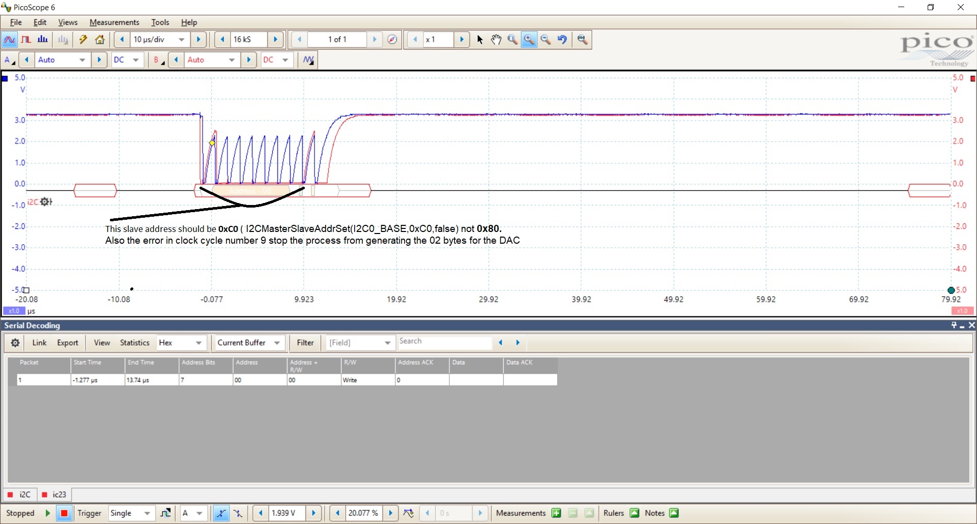
I can see on the oscilloscope that the I2C send the address 0x80 instead of 0xC0 and this causes the communication to stop as the slave wasn't selected.

I tried the MSP4725 evaluation board with the PICkit Serial analyser and the board worked as intended as I could change the voltage of the DAC output as needed.

It seems to the I2C of the TM4C1294 is at fault.


Pickit Serial Analyser: https://www.microchip.com/Developmenttools/ProductDetails/DV164122:

MSP4725 evaluation board: http://ww1.microchip.com/downloads/en/devicedoc/51669a.pdf


I am a bit surprise that the I2C didn’t work. Can anyone help me please?

 Below is the simple example:


//*****************************************************************************
//
// main()
//
//*****************************************************************************
int
main(void)
{

	static uint32_t ui32SysClkFreq, u32GetClock;
	ui32SysClkFreq = SysCtlClockFreqSet((SYSCTL_XTAL_25MHZ |
			SYSCTL_OSC_MAIN | SYSCTL_USE_PLL |
			SYSCTL_CFG_VCO_480), 120000000);


	SysCtlPeripheralEnable(SYSCTL_PERIPH_I2C0);  // enable I2C0

	while(!SysCtlPeripheralReady(SYSCTL_PERIPH_I2C0));


	SysCtlPeripheralReset(SYSCTL_PERIPH_I2C0);  // Reset I2C0

	while(!SysCtlPeripheralReady(SYSCTL_PERIPH_I2C0)) ;

	SysCtlPeripheralEnable(SYSCTL_PERIPH_GPIOB);  // enable portB (pin_B3 and Pin B2) for I2C0
	SysCtlPeripheralEnable(SYSCTL_PERIPH_GPION);    // Enable portN for LED for debugging

	// Configure SDA o PORTB PIN3
	GPIOPinConfigure(GPIO_PB3_I2C0SDA);
	GPIOPinTypeI2C(GPIO_PORTB_BASE, GPIO_PIN_3);

	// Configure SCL o PORTB PIN2
	GPIOPinConfigure(GPIO_PB2_I2C0SCL);
	GPIOPinTypeI2CSCL(GPIO_PORTB_BASE, GPIO_PIN_2);

	// Configure PORTN PIN0 and PIN1 as output
	GPIOPinTypeGPIOOutput(GPIO_PORTN_BASE, GPIO_PIN_0|GPIO_PIN_1);  // debug


	//Set I2C clock and speed to 100Kbps
	I2CMasterInitExpClk(I2C0_BASE,SysCtlClockGet(),false);  // tried this 
	// I2CMasterInitExpClk(I2C0_BASE,ui32SysClkFreq,false);  // a120Mhz

	while(I2CMasterBusy(I2C0_BASE));

	I2CMasterSlaveAddrSet(I2C0_BASE,0xC0,false);   set slave address 

	I2CMasterControl(I2C0_BASE,I2C_MASTER_CMD_BURST_SEND_START);

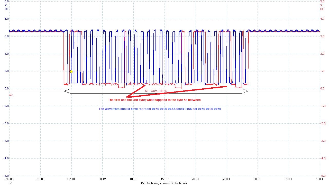
	I2CMasterDataPut(I2C0_BASE,0x0A);   // send the DAC’s 4 MSB bits

	I2CMasterControl(I2C0_BASE,I2C_MASTER_CMD_BURST_SEND_CONT);

	while(I2CMasterBusy(I2C0_BASE));

	I2CMasterDataPut(I2C0_BASE,0xAA); // send the DAC’s 8 LSB bits

	I2CMasterControl(I2C0_BASE,I2C_MASTER_CMD_BURST_SEND_FINISH);
	while(I2CMasterBusy(I2C0_BASE));

	I2CMasterControl(I2C0_BASE,I2C_MASTER_CMD_BURST_SEND_STOP);

	GPIOPinWrite(GPIO_PORTN_BASE, GPIO_PIN_0|GPIO_PIN_1, 3);

	while(1)
	{
		SysCtlDelay(ui32SysClkFreq / (3 * 5) );
		GPIOPinWrite(GPIO_PORTN_BASE, GPIO_PIN_0, 1);
		SysCtlDelay(ui32SysClkFreq / (3 * 5) );
		GPIOPinWrite(GPIO_PORTN_BASE, GPIO_PIN_0, 0);
	}
}

  •  Connections:

    TM4C1294                                              MCP4725 Eval Board

    PB3                                                SDA

    PB2                                               SCL

    GND                                             GND

    3.3V                                              VDD


    Scope Legend: Blue colour  SCL

    Red Colour :SDA


  • Hello Rab,

    Please swap your DataPut and Control calls so DataPut precedes the Control calls as the Control call triggers the data to be sent so if DataPut is used after, then the data isn't actually loaded for that transmission. See if having the proper sequence in place then also lets the Slave Address come out correctly, I think the I2C driver may be getting scrambled a bit by your attempt to send data when data hasn't been given yet.

    Also you may find this I2C document useful as you work with the I2C module: www.ti.com/.../spma073.pdf
  • Hi Ralph and thank you for the reply.

    "Please swap your DataPut and Control calls so DataPut precedes the Control calls" 

    I already tried that but it  didn't work.

    I  think the problem is with the pull up resistors. The DAC Eval board uses 5K pull up resistors and I think that it is creating the saw like waveform. Probably it is like an open-circuit considering the TM4C1294 is powered by 3.3V.  The Microchip PiCkit Serial Analyser can be used to try out the DAC Eval board. I tried both 5V and 3.3V and in both occasion did work

    I would like to try a lower values and see if that resolve the issue.


  • An update!

    I reduced the pull up resistor to 1K and tried again but I am still getting the same results; the slave address was 0xC0 and the I2C0 send 0x7F. I also tried I2C2 (Port N (4:5)) but no luck again.

    I was optimistic that was the faults but now I am started getting doubt about the microcontroller I2C engine itself. It is not sending the right slave address as it is set in the     I2CMasterSlaveAddrSet(I2C0_BASE,0xC0,false).  

    I tried again  with the original Microchip PICkit  Serial analyser and it did work as intended.

    Does I2C work for TM4C129x microcontroller in the first place or am I missing something?

    Regards,

    I2C results when tried with Microchip Pickit serial analyser 

  • Hello Rab,

    The I2C works, and the code you presented looked okay to me. When I am back in the office on Monday I will try and run that code and see if I can replicate the issue on my own EK-TM4C1294XL LaunchPad.
  • i Ralph and thank you for taking interest in this subject.

    "The I2C works": out of "desperation" I started have a doubt but inside I though there is no way that the I2C doesn't work or at least the hardware. 

    "I am back in the office on Monday I will try and run that code": Please can you try the code below?

    I looked at the slave register I2C_MCA_SA and it contains 0x80 instead of 0xC0. Also the value 0x80 is shown the oscilloscope screen shot. Maybe the API I2CMasterSlaveAddrSet(I2C0_BASE,0xC0,false) is causing all this problem. Again this is write operation but it shown a receive operation.

    I will try to write the slave address directly into the register I2C_MCA_SA and see what happened?

    The code:


    //*****************************************************************************
    //
    // main()
    //
    //*****************************************************************************
    int
    main(void)
    {
        static uint32_t ui32SysClkFreq, u32GetClock;
        ui32SysClkFreq = SysCtlClockFreqSet((SYSCTL_XTAL_25MHZ |
                                               SYSCTL_OSC_MAIN | SYSCTL_USE_PLL |
                                               SYSCTL_CFG_VCO_480), 120000000);
       // u32GetClock=SysCtlClockGet();
        SysCtlPeripheralEnable(SYSCTL_PERIPH_I2C0);  // enable I2C0
        while(!SysCtlPeripheralReady(SYSCTL_PERIPH_I2C0)); // Wait for the I2C0 module to be ready.

        SysCtlPeripheralReset(SYSCTL_PERIPH_I2C0);  // Reset I2C0
        while(!SysCtlPeripheralReady(SYSCTL_PERIPH_I2C0)) ;

        SysCtlPeripheralEnable(SYSCTL_PERIPH_GPIOB);  // enable portB (pin_B3 and Pin B2) for I2C0
        while(!SysCtlPeripheralReady(SYSCTL_PERIPH_GPIOB)) ;
        SysCtlPeripheralEnable(SYSCTL_PERIPH_GPION);    // Enable portN for LED
        while(!SysCtlPeripheralReady(SYSCTL_PERIPH_GPION)) ; // give it time to settle
        // Configure SDA on PORTB PIN3
        GPIOPinConfigure(GPIO_PB3_I2C0SDA);
        GPIOPinTypeI2C(GPIO_PORTB_BASE, GPIO_PIN_3);
        while(!SysCtlPeripheralReady(SYSCTL_PERIPH_I2C0)) ; // give it time to settle
        // Configure SCL o PORTB PIN2
        GPIOPinConfigure(GPIO_PB2_I2C0SCL);
        GPIOPinTypeI2CSCL(GPIO_PORTB_BASE, GPIO_PIN_2);
        while(!SysCtlPeripheralReady(SYSCTL_PERIPH_I2C0)) ; // give it time to settle
        // Configure PORTN PIN0 and PIN1 as output for debugging
     GPIOPinTypeGPIOOutput(GPIO_PORTN_BASE, GPIO_PIN_0|GPIO_PIN_1);

     //Set I2C clock and speed to 100Kbps
     I2CMasterInitExpClk(I2C0_BASE,ui32SysClkFreq,false);   // tried this
    // I2CMasterInitExpClk(I2C0_BASE,SysCtlClockGet(),false);  // and this
     while(I2CMasterBusy(I2C0_BASE)); // give it time to settle
     // HWREG(I2C0_BASE+I2C_O_FIFOCTL);
     I2CMasterSlaveAddrSet(I2C0_BASE,0xC0,false);  // set slave address
     SysCtlDelay(ui32SysClkFreq / (3 * 5) ); // allow intialisation to settle
     I2CMasterDataPut(I2C0_BASE,0x0A);  // 1st byte for DAC
     I2CMasterControl(I2C0_BASE,I2C_MASTER_CMD_BURST_SEND_START);
     while(I2CMasterBusy(I2C0_BASE));  // not busy
     I2CMasterDataPut(I2C0_BASE,0xAA); // 2nd byte for DAC
     I2CMasterControl(I2C0_BASE,I2C_MASTER_CMD_BURST_SEND_FINISH);
     while(I2CMasterBusy(I2C0_BASE));  // not busy
     I2CMasterControl(I2C0_BASE,I2C_MASTER_CMD_BURST_SEND_STOP);
     while(I2CMasterBusy(I2C0_BASE));  // not busy

     GPIOPinWrite(GPIO_PORTN_BASE, GPIO_PIN_0|GPIO_PIN_1, 3);

        while(1)
        {
            SysCtlDelay(ui32SysClkFreq / (3 * 5) );
            GPIOPinWrite(GPIO_PORTN_BASE, GPIO_PIN_0, 1);
            SysCtlDelay(ui32SysClkFreq / (3 * 5) );
            GPIOPinWrite(GPIO_PORTN_BASE, GPIO_PIN_0, 0);
         }
    }
    Debugging output :


  • Just an update.

    I commented I2CMasterSlaveAddrSet(I2C0_BASE,0xC0,false) and replaced it with HWREG(I2C0_BASE+0x0000)=0xC0 so I can write the slave address directly to I2CMCA register.

    I also commented lines 149-150.

    It seems now I can see in the debugger that I2CMCA register has the correct address which is 0xC0. Also the DAC Eval board output the right programmed voltage. I have tried one value at the time and it did work as intended. I need to try it in a loop and see.

    So far the API  I2CMasterSlaveAddrSet seems to be writing the wrong slave address to the register I2CMCA. I don't know if it is a bug or something else.

    I am using tivaware_c_series_2_1_4_178 under CCS 8.3.0.


  • Hello Rab,

    Thank you for this latest post, it just jogged my mind properly. While trying to be a weekend warrior I forgot something fundamental about how I2C slave addressing works with the I2CMasterSlaveAddrSet API. It is expecting a 7 bit address. If you look at the API details in i2c.c in driverlib, you will see that it bit shifts the address by 1 and then appends the Receive flag at the end of it. As such, you will want to use the API like this:

        I2CMasterSlaveAddrSet(I2C0_BASE,0x60,false);

    This will then actually output 0xC0 on the bus after bit shifting and placing the Receive bit (which is 0) onto the end.

    Sorry I didn't remember this right off the bat.

  • HI Ralph
    Thank you for keeping up with this post and I am sorry to spoil your weekend. :)
    That make sense now but I didn't expect that to be the case. Using the term "slave address" took me in completely different direction.
    For this device; the value 0xC0 is the slave address when you want to write to the slave and the value 0xC1 is used when you want to read or receive data from the device. In both case the first LSB bit indicate the direction of the data.
    I though the API take the value as inputted by the user and assign the 7-bit value to the I2CMCA register and the LSB bit (0 or 1) to the R/S bit.

    Thank you for clarifying that. Really appreciate it.
  • Hi again,

    It seems that I spoke too soon.

    The issue was resolve when sending for example 2 byte of the data using  API Start and finish but if you want send let say data in multiple of 2 by using the API CONT, the program seems to send only the first ( START) and the last byte (FINISHED) and ignore the CONT statement. In the other hand if I run the program by steps ie START then check, then CONT then Check the scope, I can see that the API CONT is sending the byte.

    The data I wanted to send was 

    Slave address: 0xC0  was sent on the scope 

    1st byte : 0x00 was sent on the scope 

    2nd byte: 0xAA not seeing on the scope

    3d byte: 0x0B not seeing on the scope 

    4th byte :0x66 was sent on the scope 

    It seems to me that the line  I2CMasterControl(I2C0_BASE,I2C_MASTER_CMD_BURST_SEND_CONT); is not running for unknown reasons

    Please see code  and oscillscope screenshot below:

    //*****************************************************************************
    //
    // main()
    //
    //*****************************************************************************
    int
    main(void)
    {
        static uint32_t ui32SysClkFreq, u32GetClock;
        ui32SysClkFreq = SysCtlClockFreqSet((SYSCTL_XTAL_25MHZ |
                                               SYSCTL_OSC_MAIN | SYSCTL_USE_PLL |
                                               SYSCTL_CFG_VCO_480), 120000000);
       // u32GetClock=SysCtlClockGet();
        SysCtlPeripheralEnable(SYSCTL_PERIPH_I2C0);  // enable I2C0
        while(!SysCtlPeripheralReady(SYSCTL_PERIPH_I2C0)); // Wait for the I2C0 module to be ready.

        SysCtlPeripheralReset(SYSCTL_PERIPH_I2C0);  // Reset I2C0
        while(!SysCtlPeripheralReady(SYSCTL_PERIPH_I2C0)) ;

        SysCtlPeripheralEnable(SYSCTL_PERIPH_GPIOB);  // enable portB (pin_B3 and Pin B2) for I2C0
        while(!SysCtlPeripheralReady(SYSCTL_PERIPH_GPIOB)) ;
        SysCtlPeripheralEnable(SYSCTL_PERIPH_GPION);    // Enable portN for LED
        while(!SysCtlPeripheralReady(SYSCTL_PERIPH_GPION)) ; // give it time to settle
        // Configure SDA on PORTB PIN3
        GPIOPinConfigure(GPIO_PB3_I2C0SDA);
        GPIOPinTypeI2C(GPIO_PORTB_BASE, GPIO_PIN_3);
        while(!SysCtlPeripheralReady(SYSCTL_PERIPH_I2C0)) ; // give it time to settle
        // Configure SCL o PORTB PIN2
        GPIOPinConfigure(GPIO_PB2_I2C0SCL);
        GPIOPinTypeI2CSCL(GPIO_PORTB_BASE, GPIO_PIN_2);
        while(!SysCtlPeripheralReady(SYSCTL_PERIPH_I2C0)) ; // give it time to settle
        // Configure PORTN PIN0 and PIN1 as output for debugging
     GPIOPinTypeGPIOOutput(GPIO_PORTN_BASE, GPIO_PIN_0|GPIO_PIN_1);

     //Set I2C clock and speed to 100Kbps
     I2CMasterInitExpClk(I2C0_BASE,ui32SysClkFreq,false);   // tried this
    // I2CMasterInitExpClk(I2C0_BASE,SysCtlClockGet(),false);  // and this
     while(I2CMasterBusy(I2C0_BASE)); // give it time to settle
      //HWREG(I2C0_BASE+I2C_O_FIFOCTL);
    // I2CMasterSlaveAddrSet(I2C0_BASE,0xC0,false);  // set slave address
     HWREG(I2C0_BASE+0x0000)=0xC0;
     SysCtlDelay(ui32SysClkFreq / (3 * 5) ); // allow intialisation to settle
     I2CMasterDataPut(I2C0_BASE,0x00);  // 1st byte for DAC
     I2CMasterControl(I2C0_BASE,I2C_MASTER_CMD_BURST_SEND_START);
     while(I2CMasterBusy(I2C0_BASE));  // not busy
     I2CMasterDataPut(I2C0_BASE,0xAA); // 2nd byte for DAC
     I2CMasterControl(I2C0_BASE,I2C_MASTER_CMD_BURST_SEND_CONT);
     while(I2CMasterBusy(I2C0_BASE));  // not busy
     I2CMasterDataPut(I2C0_BASE,0x0B);  // 1st byte for DAC
     I2CMasterControl(I2C0_BASE,I2C_MASTER_CMD_BURST_SEND_CONT);
     while(I2CMasterBusy(I2C0_BASE));  // not busy

        I2CMasterDataPut(I2C0_BASE,0x66); // 2nd byte for DAC
     I2CMasterControl(I2C0_BASE,I2C_MASTER_CMD_BURST_SEND_FINISH);
     while(I2CMasterBusy(I2C0_BASE));  // not busy
     GPIOPinWrite(GPIO_PORTN_BASE, GPIO_PIN_0|GPIO_PIN_1, 3);

        while(1)
        {
            SysCtlDelay(ui32SysClkFreq / (3 * 5) );
            GPIOPinWrite(GPIO_PORTN_BASE, GPIO_PIN_0, 1);
            SysCtlDelay(ui32SysClkFreq / (3 * 5) );
            GPIOPinWrite(GPIO_PORTN_BASE, GPIO_PIN_0, 0);
         }
    }
    Oscilloscope screenshot:

  • Hello rab,

    It looks to me like this may be a hardware problem or an issue with that analyzer as with your code I got the following output on another TM4C LaunchPad. I will try with the TM4C1294 tomorrow but I did not have time to setup a board with pull-up's on it to test with.

  • Hi Ralph,

    What is the name of the analyser you are using?
    I am using Picoscope 2205A which is an USB oscilloscope and it can be setup to decode serial interface such as I2C.
    The confusing thing is when I use debugging step by step ( using Run to line ) I can see that the API CONT is sending the byte.
    But when I try to send the 4 bytes in one go, that doesn't work.
    When I tried the DAC Eval board with the Microchip PicKit Serial, it works and I can see all the salve address plus 4 bytes were sent.
    This is baffling?
    Best regards,
  • Hi Rab,

      Can you reference the workaround in this post and see if it makes a difference. 

    Basically, replace all the occurrences of the below line 

     while(I2CMasterBusy(I2C0_BASE));  // not busy

    by  

     while(!I2CMasterBusy(I2C0_BASE));  // add this line in addition to the original line

     while(I2CMasterBusy(I2C0_BASE));  // not busy

  • Hello Charles,

    Excellent! 

    Thank you very much for the help.

    It is working now. I can send as many bytes as I want between  API START and FINISHED

    It never came to my mind to put that statement. I tried to put delays. That was the most logical things.

    I don't know if this is a just one case or it needs to be highlighted in the TIVA C Serie Library manual so other user will  not have to go through this confusing situation.

    Best regards,

  • Hi Rab,
    Glad that it works. I agree this needs to be highlighted so people don't run into the same problem again.