This thread has been locked.

If you have a related question, please click the "Ask a related question" button in the top right corner. The newly created question will be automatically linked to this question.

CCS/TM4C1294NCPDT: Hardware Watchpoint Not Being Triggered

Part Number: TM4C1294NCPDT

Tool/software: Code Composer Studio

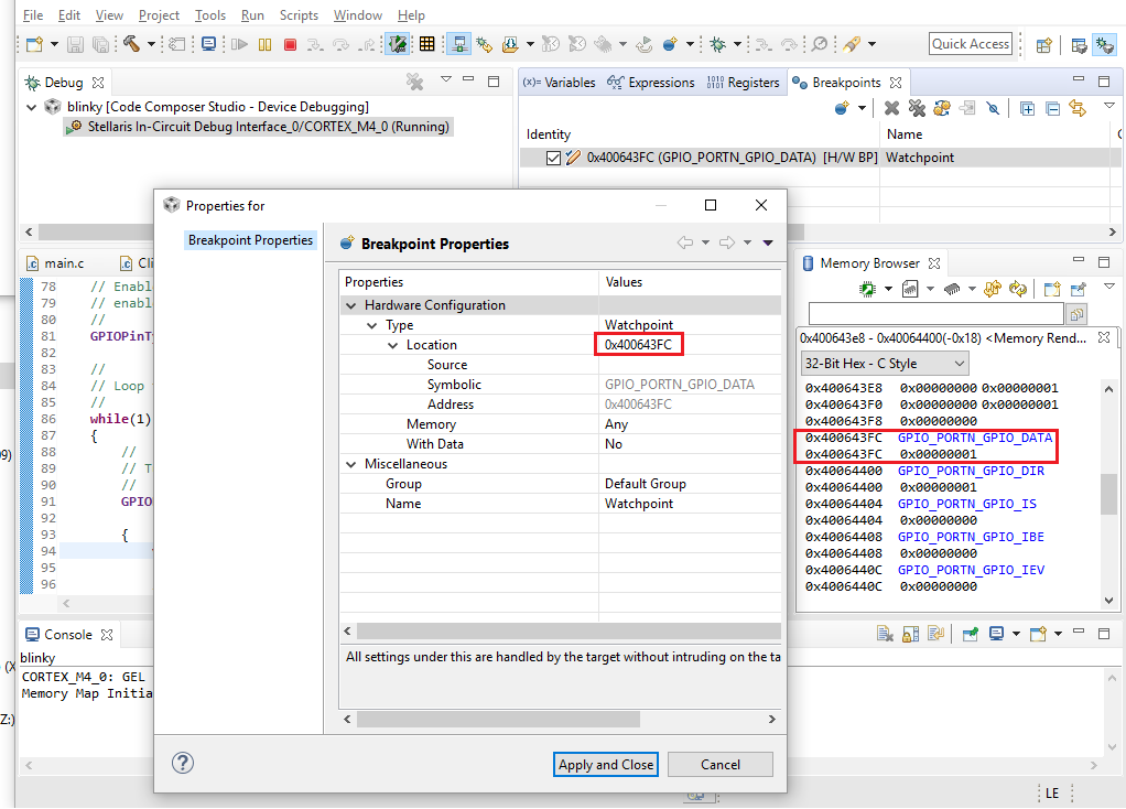
I'm having trouble getting a hardware watchpoint (breakpoint) to trigger.  I'm trying to do so on the blinky example.  The example simply toggles pin 0 of port N to blink the LED.  As shown in the screenshot below, this is at address 0x400643FC.  By all accounts I have the watchpoint configured properly as shown below, however as the LED blinks on/off the program never breaks.  Anyone have any ideas?

  • Hi Terence,
    Please refer to the datasheet on the Data Register Operation for GPIO module for details. Basically, each 8-bit GPIO port has 256 combinations. Each combination is memory mapped to an unique address to facilitate bit writing as Cortex-M4 core does not naively support bit writing. The offset 0x3FC would mean that you are writing to all 8-bits in Port N.

    Please also refer to the below post which may also help.
    e2e.ti.com/.../2880239

    Another way to understand is to look at the how GPIOPinWrite. See below how the ui8Pins being shifted by 4 as an offset address.

    //*****************************************************************************
    //
    //! Writes a value to the specified pin(s).
    //!
    //! \param ui32Port is the base address of the GPIO port.
    //! \param ui8Pins is the bit-packed representation of the pin(s).
    //! \param ui8Val is the value to write to the pin(s).
    //!
    //! Writes the corresponding bit values to the output pin(s) specified by
    //! \e ui8Pins. Writing to a pin configured as an input pin has no effect.
    //!
    //! The pin(s) are specified using a bit-packed byte, where each bit that is
    //! set identifies the pin to be accessed, and where bit 0 of the byte
    //! represents GPIO port pin 0, bit 1 represents GPIO port pin 1, and so on.
    //!
    //! \return None.
    //
    //*****************************************************************************
    void
    GPIOPinWrite(uint32_t ui32Port, uint8_t ui8Pins, uint8_t ui8Val)
    {
    //
    // Check the arguments.
    //
    ASSERT(_GPIOBaseValid(ui32Port));

    //
    // Write the pins.
    //
    HWREG(ui32Port + (GPIO_O_DATA + (ui8Pins << 2))) = ui8Val;
    }
  • Thank you, Charles. I think I understand now. I need to set my watchpoint address to 0x40064004.