This thread has been locked.

If you have a related question, please click the "Ask a related question" button in the top right corner. The newly created question will be automatically linked to this question.

CCP EdgeTime Event Capture

Guru 55913 points
Part Number: TM4C1294KCPDT

Datasheet section for Edge Time measures seems to  typo the snapshot for prescaler register. Snapshot mode registers are for periodic and Oneshot modes as confirmed by register text. The other point is the edge time mode as properly configured does capture events interrupts. The results captured GPTMTnR, GPTMnPR registers return unstable values for stable input signal CCP and POS edge events interrupts. The timer is being configured PIOSC clock source, 25ms down count, positive edge events capture interrupts for 20Hz-220Hz input signal, no real issues here.

Figure 13-3 on page 963 shows how input edge timing mode works. In the diagram, it is assumed that the start value of the timer is the default value of 0xFFFF, and the timer is configured to capture rising edge events. Each time a rising edge event is detected, the current count value is loaded into the GPTMTnR and GPTMTnPS registers, and is held there until another rising edge is detected (at which point the new count value is loaded into the GPTMTnR and GPTMTnPS registers).

Register 24: GPTM Timer B Prescale Snapshot (GPTMTnPS), offset 0x060 For 16-/32-bit wide GPTM, this register shows the current value of the Timer B prescaler for periodic snapshot mode.

Register 15: GPTM Timer B Prescale (GPTMTnPR), offset 0x03C This register allows software to extend the range of the timers when they are used individually. When in one-shot or periodic down count modes, this register acts as a true prescaler for the timer counter. When acting as a true prescaler, the prescaler counts down to 0 before the value in the GPTMTnR and GPTMTnV registers are incremented. In all other individual/split modes, this register is a linear extension of the upper range of the timer counter, holding bits 23:16 in the 16-bit modes of the 16/32-bit GPTM.

13.4.4 Initilization & Configuration text differs with Fig13-3 which states to get the snapshot prescale register GPTMTnPS for the return results. Register GPTMTnPS is 0x0 ever interrupt time!

5. If a prescaler is to be used, write the prescale value to the GPTM Timer n Prescale Register (GPTMTnPR).
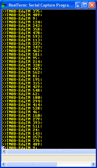
Capture Results:


  • BP101,
    Do you have a question?
  • Hi Bob,

    You don't see the issue with datasheet analysis of edge time stating to use Snapshot prescaler register for edge time but configuration text uses another register? Tivaware TimerConfigure() text states Snapshot is for Periodic, Oneshot modes, not edge Time mode. Besides configuring the timer for edge capture seemingly is not working as it should. Yet edge counts mode produce consistent return values in interrupt handler reading of GPTM_TnR register.

    You don't see the printed captured edge times interrupts are also not keeping constant values even when CCP input signal is constant 49.5Hz? Note the printed values are not improved by dividing down filtering for any edge jitter in CCP. Besides the edge time prescaler value is stored in the upper 23:16 of GPTM_TnR not T_nPS registers.

  • What must be done to base configuration as described 13.4.4 for GPTM_TnR register to return constant results in the interrupt handler? It's not like the CCP input signal is varying frequency. seemingly the point at which the down count reaches GPTMTnR=X and GPTMTnR=Y are not locking to the CCP rising edge events and frequently bottom out near GPTMTnR=Z. Nobody cares about GPTMTnR=Z that is not considered valid edge time seemingly represent timeout events.

    Even if we subtract GPTMTnR=Y from have had saved GPTMTnR=X in first interrupt cycle the printed values are still not consistent every other interrupt cycle. The subtraction of a saved variable typically stops GPTM_TnR time value from growing in the printed variable.  And 49.5Hz CCP is well above 25ms which should easily count down to 40Hz in GPTM_TnR.

    25ms timer load values:

        /* Load upper bits TbPR 24 bit CCP edge time
         * for 25ms/40hz minimum edge time */
        MAP_TimerPrescaleSet(TIMER0_BASE, TIMER_B, 0x0006);
    
        /* Load lower bits TbILR 25ms/40Hz edge time */
        MAP_TimerLoadSet(TIMER0_BASE, TIMER_B, 0x1A80); 
    
        /* Configure edge polarity capture events for CCP1. */
        MAP_TimerControlEvent(TIMER0_BASE, TIMER_B, TIMER_EVENT_POS_EDGE);

  • Hi Bob,

    Seemingly obvious that we must enable Snap Shot mode in GPTM configuration for PS registers to produce valid results. The configuration and edge time analysis sections make no mention to enable Snap Shot mode (TnSNAPS) bit in TnMR.

    There is a bit of silly in the text (below) relates Figure 13-3 GPTMTnR=X and GPTMTnR=Y results even being readable during interrupts and application execution times. Text infers application just magically stops for the edge time results to be read between X to Y CCP input cycles. Are final results concatenated at end of cycle GPTMTnR=Z? What does "held there" mean relative to an application using the register information? What's the point of loading a new value if the first value has never been read by the application as to compare X to Y obtain CCP input frequency via F=1/p?

    No matter edge time CCP capture fails to produce consistent results even if Snap mode is enabled, the TnPS register is 0x0 during interrupts either way. Perhaps 0x0 occurs since TnR holds the prescaler results bits [23:16]? Might it be time to update the TM4C1294 datasheet with useful facts so customers don't struggle so much? This very same "inaccurate" statement below is also in Stellaris datasheets and further confused by TM4C1294 datasheet addition of TnPS register.

    Datasheet verbatim:

    Each time a rising edge event is detected, the current count value is loaded into the GPTMTnR and GPTMTnPS registers, and is held there until another rising edge is detected (at which point the new count value is loaded into the GPTMTnR and GPTMTnPS registers).