This thread has been locked.

If you have a related question, please click the "Ask a related question" button in the top right corner. The newly created question will be automatically linked to this question.

EK-TM4C123GXL: Trying to Read BME280 using I2C.

Part Number: EK-TM4C123GXL

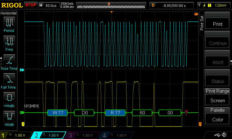
I recently bought a TM4C123 LaunchPad with BOOSTXL-SENSORS Sensor booster pack. I am trying to use the onboard BME280 sensor using Bosch API.So far, I2C read part works only for reading the device id, the I2C write part doesn't work at all. Kindly help.

#include<stdint.h>
#include<stdbool.h>
#include<stdio.h>
#include <string.h>
#include "inc/hw_ints.h"
#include "inc/hw_memmap.h"
#include "inc/hw_types.h"
#include "driverlib/gpio.h"
#include "driverlib/interrupt.h"
#include "driverlib/pin_map.h"
#include "driverlib/sysctl.h"
#include "driverlib/uart.h"
#include "driverlib/i2c.h"
#include "utils/uartstdio.h"
#include "functions.h"
#include "bme280.h"
#include "bme280_defs.h"
int8_t stream_sensor_data_normal_mode(struct bme280_dev *dev);
void print_sensor_data(struct bme280_data *comp_data);
void main()
{
    SysCtlClockSet(SYSCTL_SYSDIV_2_5 | SYSCTL_USE_PLL | SYSCTL_OSC_MAIN |
    SYSCTL_XTAL_16MHZ);
    SysCtlPeripheralEnable(SYSCTL_PERIPH_GPIOA);
    InitConsole();
    UARTprintf("UART OK \n");
    InitI2C1();
    UARTprintf("I2C OK \n");
    struct bme280_dev dev;
    int8_t rslt = BME280_OK;
    dev.dev_id = 0x77;
    dev.intf = BME280_I2C_INTF;
    dev.read = user_i2c_read;
    dev.write = user_i2c_write;
    dev.delay_ms = user_delay_ms;
    rslt = bme280_init(&dev);
    stream_sensor_data_normal_mode(&dev);
}

int8_t stream_sensor_data_normal_mode(struct bme280_dev *dev)
{
    int8_t rslt;
    uint8_t settings_sel;
    struct bme280_data comp_data;

    /* Recommended mode of operation: Indoor navigation */
    dev->settings.osr_h = BME280_OVERSAMPLING_1X;
    dev->settings.osr_p = BME280_OVERSAMPLING_16X;
    dev->settings.osr_t = BME280_OVERSAMPLING_2X;
    dev->settings.filter = BME280_FILTER_COEFF_16;
    dev->settings.standby_time = BME280_STANDBY_TIME_62_5_MS;

    settings_sel = BME280_OSR_PRESS_SEL;
    settings_sel |= BME280_OSR_TEMP_SEL;
    settings_sel |= BME280_OSR_HUM_SEL;
    settings_sel |= BME280_STANDBY_SEL;
    settings_sel |= BME280_FILTER_SEL;
    rslt = bme280_set_sensor_settings(settings_sel, dev);
    rslt = bme280_set_sensor_mode(BME280_NORMAL_MODE, dev);

    UARTprintf("Temperature, Pressure, Humidity\r\n");
    while (1) {
        /* Delay while the sensor completes a measurement */
        dev->delay_ms(1000);
        rslt = bme280_get_sensor_data(BME280_ALL, &comp_data, dev);
        print_sensor_data(&comp_data);
    }

    return rslt;
}

void print_sensor_data(struct bme280_data *comp_data)
{
#ifdef BME280_FLOAT_ENABLE
        UARTprintf("%0.2f, %0.2f, %0.2f\r\n",comp_data->temperature, comp_data->pressure, comp_data->humidity);
#else
        UARTprintf("%l, %l, %l\r\n",comp_data->temperature, comp_data->pressure, comp_data->humidity);
#endif
}


void InitConsole(void)
{
    SysCtlPeripheralEnable (SYSCTL_PERIPH_GPIOA);
    GPIOPinConfigure (GPIO_PA0_U0RX);
    GPIOPinConfigure (GPIO_PA1_U0TX);
    SysCtlPeripheralEnable (SYSCTL_PERIPH_UART0);
    UARTClockSourceSet(UART0_BASE, UART_CLOCK_SYSTEM);
    GPIOPinTypeUART(GPIO_PORTA_BASE, GPIO_PIN_0 | GPIO_PIN_1);
    UARTStdioConfig(0, 115200, SysCtlClockGet());
}

void InitI2C1(void)
{
    SysCtlPeripheralEnable (SYSCTL_PERIPH_I2C1);
    GPIOPinTypeI2C(GPIO_PORTA_BASE, GPIO_PIN_6 | GPIO_PIN_7);
    GPIOPinTypeI2CSCL(GPIO_PORTA_BASE, GPIO_PIN_6);
    GPIOPinConfigure (GPIO_PA6_I2C1SCL);
    GPIOPinConfigure (GPIO_PA7_I2C1SDA);
    I2CMasterInitExpClk(I2C1_BASE, SysCtlClockGet(), false);
}

void I2CSend(uint8_t slave_addr, uint8_t num_of_args, ...)
{   int i;
    // Tell the master module what address it will place on the bus when
    // communicating with the slave.
    I2CMasterSlaveAddrSet(I2C1_BASE, slave_addr, false);

    //stores list of variable number of arguments
    va_list vargs;

    //specifies the va_list to "open" and the last fixed argument
    //so vargs knows where to start looking
    va_start(vargs, num_of_args);

    //put data to be sent into FIFO
    I2CMasterDataPut(I2C1_BASE, va_arg(vargs, uint32_t));

    //if there is only one argument, we only need to use the
    //single send I2C function
    if (num_of_args == 1)
    {
        //Initiate send of data from the MCU
        I2CMasterControl(I2C1_BASE, I2C_MASTER_CMD_SINGLE_SEND);

        // Wait until MCU is done transferring.
        while (I2CMasterBusy(I2C1_BASE))
            ;

        //"close" variable argument list
        va_end(vargs);
    }

    //otherwise, we start transmission of multiple bytes on the
    //I2C bus
    else
    {
        //Initiate send of data from the MCU
        I2CMasterControl(I2C1_BASE, I2C_MASTER_CMD_BURST_SEND_START);

        // Wait until MCU is done transferring.
        while (I2CMasterBusy(I2C1_BASE))
            ;

        //send num_of_args-2 pieces of data, using the
        //BURST_SEND_CONT command of the I2C module
        for (i = 1; i < (num_of_args - 1); i++)
        {
            //put next piece of data into I2C FIFO
            I2CMasterDataPut(I2C1_BASE, va_arg(vargs, uint32_t));
            //send next data that was just placed into FIFO
            I2CMasterControl(I2C1_BASE, I2C_MASTER_CMD_BURST_SEND_CONT);

            // Wait until MCU is done transferring.
            while (I2CMasterBusy(I2C1_BASE))
                ;
        }

        //put last piece of data into I2C FIFO
        I2CMasterDataPut(I2C1_BASE, va_arg(vargs, uint32_t));
        //send next data that was just placed into FIFO
        I2CMasterControl(I2C1_BASE, I2C_MASTER_CMD_BURST_SEND_FINISH);
        // Wait until MCU is done transferring.
        while (I2CMasterBusy(I2C1_BASE))
            ;

        //"close" variable args list
        va_end(vargs);
    }
}

void user_delay_ms(uint32_t period)
{
    SysCtlDelay((SysCtlClockGet() / 1000) * (uint32_t) period);
}

int8_t user_i2c_read(uint8_t dev_id, uint8_t reg_addr, uint8_t *reg_data,
                     uint16_t len)
{
    int8_t rslt = 0; /* Return 0 for Success, non-zero for failure */
    /*
     * The parameter dev_id can be used as a variable to store the I2C address of the device
     */

    /*
     * Data on the bus should be like
     * |------------+---------------------|
     * | I2C action | Data                |
     * |------------+---------------------|
     * | Start      | -                   |
     * | Write      | (reg_addr)          |
     * | Stop       | -                   |
     * | Start      | -                   |
     * | Read       | (reg_data[0])       |
     * | Read       | (....)              |
     * | Read       | (reg_data[len - 1]) |
     * | Stop       | -                   |
     * |------------+---------------------|
     */
    I2CMasterSlaveAddrSet(I2C1_BASE, (uint8_t) dev_id, false);
    I2CMasterDataPut(I2C1_BASE, (uint8_t) reg_addr);
    I2CMasterControl(I2C1_BASE, I2C_MASTER_CMD_BURST_SEND_START);
    while (I2CMasterBusy (I2C1_BASE))
        ;
    I2CMasterControl(I2C1_BASE, I2C_MASTER_CMD_BURST_SEND_FINISH);
    I2CMasterSlaveAddrSet(I2C1_BASE, dev_id, true);
    while (len--)
    {
        I2CMasterControl(I2C1_BASE, I2C_MASTER_CMD_BURST_RECEIVE_START);
        while (I2CMasterBusy (I2C1_BASE))
            ;
        *reg_data = I2CMasterDataGet(I2C1_BASE);
        reg_data++;
    }
    return rslt;
}

int8_t user_i2c_write(uint8_t dev_id, uint8_t reg_addr, uint8_t *reg_data,
                      uint16_t len)
{
    int8_t rslt = 0; /* Return 0 for Success, non-zero for failure */

    /*
     * The parameter dev_id can be used as a variable to store the I2C address of the device
     */

    /*
     * Data on the bus should be like
     * |------------+---------------------|
     * | I2C action | Data                |
     * |------------+---------------------|
     * | Start      | -                   |
     * | Write      | (reg_addr)          |
     * | Write      | (reg_data[0])       |
     * | Write      | (....)              |
     * | Write      | (reg_data[len - 1]) |
     * | Stop       | -                   |
     * |------------+---------------------|
     */
    I2CSend(dev_id,1,reg_addr);
    while(len--)
    {
       I2CSend(dev_id,1,*reg_data);
       reg_data++;

    }

}

  • Hello V.Singh,

    It looks like that BoosterPack is more designed for the MSP432 devices, I don't recall us having any support for that BoosterPack on TM4C natively.

    If you are trying to port it because you need to use TM4C over MSP432, then we can try and help, but it honestly would probably be easier for you to try using it with the MSP-EXP432P401R kit it was designed to work with. Your call on that front.

    Anyways, as far as TM4C goes, I'd need to see I2C scope captures to be able to better help, but I have one suggestion to make for starters, and that is to apply the workaround shown in this post: https://e2e.ti.com/support/microcontrollers/other/f/908/p/741685/2738504#2738504

    Specifically, replace all the occurrences of this line:

    while (I2CMasterBusy(I2C1_BASE))
                ;

    With:

    while (!I2CMasterBusy(I2C1_BASE))
                ;
    while (I2CMasterBusy(I2C1_BASE))
                ;

  • I'm just trying to work with bme280, in general, as if it was on a breakout board. I added the suggested modifications and hooked up my scope and there's no activity both SDA and SCL is at '0'.
  • #ifndef FUNCTIONS_H_
    #define FUNCTIONS_H_
    
    void InitConsole(void)
    {
        SysCtlPeripheralEnable (SYSCTL_PERIPH_GPIOA);
        GPIOPinConfigure (GPIO_PA0_U0RX);
        GPIOPinConfigure (GPIO_PA1_U0TX);
        SysCtlPeripheralEnable (SYSCTL_PERIPH_UART0);
        UARTClockSourceSet(UART0_BASE, UART_CLOCK_SYSTEM);
        GPIOPinTypeUART(GPIO_PORTA_BASE, GPIO_PIN_0 | GPIO_PIN_1);
        UARTStdioConfig(0, 115200, SysCtlClockGet());
    }
    
    void InitI2C1(void)
    {
        SysCtlPeripheralEnable (SYSCTL_PERIPH_I2C1);
        GPIOPinTypeI2C(GPIO_PORTA_BASE, GPIO_PIN_6 | GPIO_PIN_7);
        GPIOPinTypeI2CSCL(GPIO_PORTA_BASE, GPIO_PIN_6);
        GPIOPinConfigure (GPIO_PA6_I2C1SCL);
        GPIOPinConfigure (GPIO_PA7_I2C1SDA);
        I2CMasterInitExpClk(I2C1_BASE, SysCtlClockGet(), false);
    }
    
    void I2CSend(uint8_t slave_addr, uint8_t num_of_args, ...)
    {   int i;
        // Tell the master module what address it will place on the bus when
        // communicating with the slave.
        I2CMasterSlaveAddrSet(I2C1_BASE, slave_addr, false);
    
        //stores list of variable number of arguments
        va_list vargs;
    
        //specifies the va_list to "open" and the last fixed argument
        //so vargs knows where to start looking
        va_start(vargs, num_of_args);
    
        //put data to be sent into FIFO
        I2CMasterDataPut(I2C1_BASE, va_arg(vargs, uint32_t));
    
        //if there is only one argument, we only need to use the
        //single send I2C function
        if (num_of_args == 1)
        {
            //Initiate send of data from the MCU
            I2CMasterControl(I2C1_BASE, I2C_MASTER_CMD_SINGLE_SEND);
    
            // Wait until MCU is done transferring.
            while (!I2CMasterBusy(I2C1_BASE))
                ;
            while (I2CMasterBusy(I2C1_BASE))
                ;
    
            //"close" variable argument list
            va_end(vargs);
        }
    
        //otherwise, we start transmission of multiple bytes on the
        //I2C bus
        else
        {
            //Initiate send of data from the MCU
            I2CMasterControl(I2C1_BASE, I2C_MASTER_CMD_BURST_SEND_START);
    
            // Wait until MCU is done transferring.
            while (I2CMasterBusy(I2C1_BASE))
                ;
    
            //send num_of_args-2 pieces of data, using the
            //BURST_SEND_CONT command of the I2C module
            for (i = 1; i < (num_of_args - 1); i++)
            {
                //put next piece of data into I2C FIFO
                I2CMasterDataPut(I2C1_BASE, va_arg(vargs, uint32_t));
                //send next data that was just placed into FIFO
                I2CMasterControl(I2C1_BASE, I2C_MASTER_CMD_BURST_SEND_CONT);
    
                // Wait until MCU is done transferring.
                while (!I2CMasterBusy(I2C1_BASE))
                    ;
                while (I2CMasterBusy(I2C1_BASE))
                    ;
            }
    
            //put last piece of data into I2C FIFO
            I2CMasterDataPut(I2C1_BASE, va_arg(vargs, uint32_t));
            //send next data that was just placed into FIFO
            I2CMasterControl(I2C1_BASE, I2C_MASTER_CMD_BURST_SEND_FINISH);
            // Wait until MCU is done transferring.
            while (!I2CMasterBusy(I2C1_BASE))
                ;
            while (I2CMasterBusy(I2C1_BASE))
                ;
    
            //"close" variable args list
            va_end(vargs);
        }
    }
    
    void user_delay_ms(uint32_t period)
    {
        SysCtlDelay((SysCtlClockGet() / 1000) * (uint32_t) period);
    }
    
    int8_t user_i2c_read(uint8_t dev_id, uint8_t reg_addr, uint8_t *reg_data,
                         uint16_t len)
    {
        int8_t rslt = 0; /* Return 0 for Success, non-zero for failure */
        /*
         * The parameter dev_id can be used as a variable to store the I2C address of the device
         */
    
        /*
         * Data on the bus should be like
         * |------------+---------------------|
         * | I2C action | Data                |
         * |------------+---------------------|
         * | Start      | -                   |
         * | Write      | (reg_addr)          |
         * | Stop       | -                   |
         * | Start      | -                   |
         * | Read       | (reg_data[0])       |
         * | Read       | (....)              |
         * | Read       | (reg_data[len - 1]) |
         * | Stop       | -                   |
         * |------------+---------------------|
         */
        I2CMasterSlaveAddrSet(I2C1_BASE, (uint8_t) dev_id, false);
        I2CMasterDataPut(I2C1_BASE, (uint8_t) reg_addr);
        I2CMasterControl(I2C1_BASE, I2C_MASTER_CMD_BURST_SEND_START);
        while (!I2CMasterBusy(I2C1_BASE))
            ;
        while (I2CMasterBusy(I2C1_BASE))
            ;
        I2CMasterControl(I2C1_BASE, I2C_MASTER_CMD_BURST_SEND_FINISH);
        I2CMasterSlaveAddrSet(I2C1_BASE, dev_id, true);
        while (len--)
        {
            I2CMasterControl(I2C1_BASE, I2C_MASTER_CMD_BURST_RECEIVE_START);
            while (!I2CMasterBusy(I2C1_BASE))
                ;
            while (I2CMasterBusy(I2C1_BASE))
                ;
            *reg_data = I2CMasterDataGet(I2C1_BASE);
            reg_data++;
        }
        return rslt;
    }
    
    int8_t user_i2c_write(uint8_t dev_id, uint8_t reg_addr, uint8_t *reg_data,
                          uint16_t len)
    {
        int8_t rslt = 0; /* Return 0 for Success, non-zero for failure */
    
        /*
         * The parameter dev_id can be used as a variable to store the I2C address of the device
         */
    
        /*
         * Data on the bus should be like
         * |------------+---------------------|
         * | I2C action | Data                |
         * |------------+---------------------|
         * | Start      | -                   |
         * | Write      | (reg_addr)          |
         * | Write      | (reg_data[0])       |
         * | Write      | (....)              |
         * | Write      | (reg_data[len - 1]) |
         * | Stop       | -                   |
         * |------------+---------------------|
         */
        I2CSend(dev_id,1,reg_addr);
        while(len--)
        {
           I2CSend(dev_id,1,*reg_data);
           reg_data++;
    
        }
    
    }
    #endif /* FUNCTIONS_H_ */


  • Hello V.Singh,

    But you see activity when you are trying to read the device ID from the device? So you are successfully able to send a slave address and a read command for the device ID, and receive that data? But when you try the write process, you are not seeing any data get sent, not even the slave address?
  • Yes, I'm able to send the slave address and read from the device register but there's no activity when I'm trying to write(doesn't send slave address or send data). Additionally, I just tried out the sensor with Arduino and the sensor works perfectly fine.
  • Hello V.Singh,

    If the slave address isn't sent, can you double check the SCL or SDA lines aren't being held low by the slave device? I highly doubt that is whats happening, but it would rule out hardware as an issue.

    As long as the lines are available, then I would expect a software issue to be responsible. Have you tried breakpoints to see if the functions to write are being reached?

    I didn't suspect the sensor to have any issues, but thanks for that check.

  • The read and write functions are working now. Although only one I2C transaction takes place as depicted in the attached image.I suspect that there's some problem with the API integration. As far as Hardware goes it seems to work fine. As far as code goes I only changed

     UARTprintf("%d, %d, %d\r\n",comp_data->temperature, comp_data->pressure, comp_data->humidity);
    
     FROM
    UARTprintf("%l, %l, %l\r\n",comp_data->temperature, comp_data->pressure, comp_data->humidity);

    the console constantly reads 0, 8138076, 102400 but there's no activity on the bus!

  • Hello V.Singh,

    That clock looks really bad. What are the pull-up resistors you are using? You may want to reference this app note: www.ti.com/.../slva689.pdf

    If the pull-ups are not set right, you may see signals but not get proper data, from what I am seeing, that seems like what you may be going up against now that you have the API's at least trying to communicate.