Part Number: TM4C1294NCPDT
Other Parts Discussed in Thread: TM4C123GH6PM
TM4C1294NCPDT CAN BUS Error
I am new to CAN interface programming. I tried to establish CAN communication between 2 TIVAC boards using MCP2551 transceiver. I got some help from ohmninja website for basic CAN programming. my basic idea is to read sensor value through ADC in one TIVAC and send the same to other TIVAC through CAN interface. The transmit and receive programs gets compiled successfully and I can able to build the project. But once I check the UART for output I end up with CAN BUS error. I post my program and output screenshot plz do help
Transmit Code
#include <stdint.h>
#include <stdbool.h>
#include "inc/hw_memmap.h"
#include "inc/hw_types.h"
#include "driverlib/debug.h"
#include "driverlib/sysctl.h"
#include "driverlib/gpio.h"
#include "driverlib/adc.h"
#include "inc/hw_memmap.h"
#include "driverlib/uart.h"
#include "driverlib/pin_map.h"
#include "utils/uartstdio.h"
#include "inc/hw_can.h"
#include "inc/hw_ints.h"
#include "driverlib/can.h"
#include "driverlib/interrupt.h"
#include "utils/uartstdio.h"

unsigned int sysClock;

volatile bool errFlag = 0; // transmission error flag
unsigned int sysClock; // clockspeed in hz

// CAN interrupt handler
void CANIntHandler(void) {

    unsigned long status = CANIntStatus(CAN1_BASE, CAN_INT_STS_CAUSE); // read interrupt status

    if(status == CAN_INT_INTID_STATUS) { // controller status interrupt
        status = CANStatusGet(CAN1_BASE, CAN_STS_CONTROL); // read back error bits, do something with them?
        errFlag = 1;
    } else if(status == 1) { // message object 1
        CANIntClear(CAN1_BASE, 1); // clear interrupt
        errFlag = 0; // clear any error flags
    } else { // should never happen
        UARTprintf("Unexpected CAN bus interrupt\n");
    }
}

void delay(unsigned int milliseconds) {
    SysCtlDelay((sysClock / 3) * (milliseconds / 1000.0f));
}
int main(void)
{
    uint32_t ui32ACCValues[4];
    volatile uint32_t ui32AccX;
    volatile uint32_t ui32AccY;
    volatile uint32_t ui32AccZ;
    tCANMsgObject msg; // the CAN message object
        unsigned int msgData; // the message data is four bytes long which we can allocate as an int32
        unsigned char *msgDataPtr = (unsigned char *)&msgData; // make a pointer to msgData so we can access individual bytes

    SysCtlClockFreqSet((SYSCTL_XTAL_25MHZ | SYSCTL_OSC_MAIN | SYSCTL_USE_PLL | SYSCTL_CFG_VCO_480), 120000000);

    sysClock = SysCtlClockFreqSet((SYSCTL_XTAL_25MHZ | SYSCTL_OSC_MAIN | SYSCTL_USE_PLL | SYSCTL_CFG_VCO_480), 120000000);

        // Set up debugging UART
        SysCtlPeripheralEnable(SYSCTL_PERIPH_GPIOA); // enable UART0 GPIO peripheral
        SysCtlPeripheralEnable(SYSCTL_PERIPH_UART0);
        GPIOPinConfigure(GPIO_PA0_U0RX);
        GPIOPinConfigure(GPIO_PA1_U0TX);
        GPIOPinTypeUART(GPIO_PORTA_BASE, GPIO_PIN_0 | GPIO_PIN_1);
        UARTStdioConfig(0, 115200, sysClock); // 115200 baud

    SysCtlPeripheralEnable(SYSCTL_PERIPH_ADC0);
    SysCtlPeripheralEnable(SYSCTL_PERIPH_GPIOE);

    GPIOPinTypeADC(GPIO_PORTE_BASE, GPIO_PIN_0 | GPIO_PIN_1 | GPIO_PIN_2 );

    ADCSequenceConfigure(ADC0_BASE, 1, ADC_TRIGGER_PROCESSOR, 0);
    ADCSequenceStepConfigure(ADC0_BASE, 1, 0, ADC_CTL_CH3);
    ADCSequenceStepConfigure(ADC0_BASE, 1, 1, ADC_CTL_CH2);
    ADCSequenceStepConfigure(ADC0_BASE, 1, 2, ADC_CTL_CH1|ADC_CTL_IE|ADC_CTL_END);

    ADCSequenceEnable(ADC0_BASE, 1);

    SysCtlPeripheralEnable(SYSCTL_PERIPH_GPIOB); // enable CAN1 GPIO peripheral
    GPIOPinConfigure(GPIO_PB0_CAN1RX);
    GPIOPinConfigure(GPIO_PB1_CAN1TX);
    GPIOPinTypeCAN(GPIO_PORTB_BASE, GPIO_PIN_0 | GPIO_PIN_1);
    SysCtlPeripheralEnable(SYSCTL_PERIPH_CAN1);
    CANInit(CAN1_BASE);
    CANBitRateSet(CAN1_BASE, sysClock, 500000);
    CANIntRegister(CAN1_BASE, CANIntHandler); // use dynamic vector table allocation
    CANIntEnable(CAN1_BASE, CAN_INT_MASTER | CAN_INT_ERROR | CAN_INT_STATUS);
    IntEnable(INT_CAN1);
    CANEnable(CAN1_BASE);

    // Set up msg object
    msgData = 0;
    msg.ui32MsgID = 1;
    msg.ui32MsgIDMask = 0;
    msg.ui32Flags = MSG_OBJ_TX_INT_ENABLE;
    msg.ui32MsgLen = sizeof(msgDataPtr);
    msg.pui8MsgData = msgDataPtr;


    while(1)
    {
        ADCIntClear(ADC0_BASE, 1);
        ADCProcessorTrigger(ADC0_BASE, 1);
        while(!ADCIntStatus(ADC0_BASE, 1, false))
        {
        }
        ADCSequenceDataGet(ADC0_BASE, 1, ui32ACCValues);
        ui32AccX = ui32ACCValues[0];
        ui32AccY = ui32ACCValues[1];
        ui32AccZ = ui32ACCValues[2];
        UARTprintf("Analog Voltage\tR: %d\tY: %d\tB: %d\n",ui32AccX, ui32AccY,ui32AccZ); // write colour to UART for debugging

        CANMessageSet(CAN1_BASE, 1, &msg, MSG_OBJ_TYPE_TX); // send as msg object 1

                delay(100); // wait 100ms

                if(errFlag) { // check for errors
                    UARTprintf("CAN Bus Error\n");
                }

        delay(1000); // wait 100ms

    }
    return 0;
}
receive code
/*
* CAN bus LED controller slave firmware
* Written for TI Tiva TM4C123GH6PM
*/
* CAN bus LED controller slave firmware
* Written for TI Tiva TM4C123GH6PM
*/
#include <stdint.h>
#include <stdbool.h>
#include "inc/hw_memmap.h"
#include "inc/hw_types.h"
#include "driverlib/debug.h"
#include "driverlib/sysctl.h"
#include "driverlib/gpio.h"
#include "driverlib/adc.h"
#include "inc/hw_memmap.h"
#include "driverlib/uart.h"
#include "driverlib/pin_map.h"
#include "utils/uartstdio.h"
#include "inc/hw_can.h"
#include "inc/hw_ints.h"
#include "driverlib/can.h"
#include "driverlib/interrupt.h"
#include "utils/uartstdio.h"
volatile bool rxFlag = 0; // msg recieved flag
volatile bool errFlag = 0; // error flag
volatile bool errFlag = 0; // error flag
// CAN interrupt handler
void CANIntHandler(void) {
void CANIntHandler(void) {
unsigned long status = CANIntStatus(CAN0_BASE, CAN_INT_STS_CAUSE); // read interrupt status
if(status == CAN_INT_INTID_STATUS) { // controller status interrupt
status = CANStatusGet(CAN1_BASE, CAN_STS_CONTROL);
errFlag = 1;
} else if(status == 1) { // msg object 1
CANIntClear(CAN1_BASE, 1); // clear interrupt
rxFlag = 1; // set rx flag
errFlag = 0; // clear any error flags
} else { // should never happen
UARTprintf("Unexpected CAN bus interrupt\n");
}
}
status = CANStatusGet(CAN1_BASE, CAN_STS_CONTROL);
errFlag = 1;
} else if(status == 1) { // msg object 1
CANIntClear(CAN1_BASE, 1); // clear interrupt
rxFlag = 1; // set rx flag
errFlag = 0; // clear any error flags
} else { // should never happen
UARTprintf("Unexpected CAN bus interrupt\n");
}
}
int main(void) {
tCANMsgObject msg; // the CAN msg object
unsigned char msgData[8]; // 8 byte buffer for rx message data
unsigned char msgData[8]; // 8 byte buffer for rx message data
// Run from crystal at 50Mhz
SysCtlClockFreqSet((SYSCTL_XTAL_25MHZ | SYSCTL_OSC_MAIN | SYSCTL_USE_PLL | SYSCTL_CFG_VCO_480), 120000000);
SysCtlClockFreqSet((SYSCTL_XTAL_25MHZ | SYSCTL_OSC_MAIN | SYSCTL_USE_PLL | SYSCTL_CFG_VCO_480), 120000000);
// Set up debugging UART
SysCtlPeripheralEnable(SYSCTL_PERIPH_GPIOA);
SysCtlPeripheralEnable(SYSCTL_PERIPH_UART0);
GPIOPinConfigure(GPIO_PA0_U0RX);
GPIOPinConfigure(GPIO_PA1_U0TX);
GPIOPinTypeUART(GPIO_PORTA_BASE, GPIO_PIN_0 | GPIO_PIN_1);
UARTStdioConfig(0, 115200, SysCtlClockGet());
SysCtlPeripheralEnable(SYSCTL_PERIPH_GPIOA);
SysCtlPeripheralEnable(SYSCTL_PERIPH_UART0);
GPIOPinConfigure(GPIO_PA0_U0RX);
GPIOPinConfigure(GPIO_PA1_U0TX);
GPIOPinTypeUART(GPIO_PORTA_BASE, GPIO_PIN_0 | GPIO_PIN_1);
UARTStdioConfig(0, 115200, SysCtlClockGet());
SysCtlPeripheralEnable(SYSCTL_PERIPH_GPIOB); // enable CAN1 GPIO peripheral
GPIOPinConfigure(GPIO_PB0_CAN1RX);
GPIOPinConfigure(GPIO_PB1_CAN1TX);
GPIOPinTypeCAN(GPIO_PORTB_BASE, GPIO_PIN_0 | GPIO_PIN_1);
SysCtlPeripheralEnable(SYSCTL_PERIPH_CAN1);
CANInit(CAN1_BASE);
CANBitRateSet(CAN1_BASE, SysCtlClockGet(), 500000);
CANIntRegister(CAN1_BASE, CANIntHandler); // use dynamic vector table allocation
CANIntEnable(CAN1_BASE, CAN_INT_MASTER | CAN_INT_ERROR | CAN_INT_STATUS);
CANIntClear(CAN1_BASE,CAN_INT_STATUS);
IntEnable(INT_CAN1);
CANEnable(CAN1_BASE);
// Use ID and mask 0 to recieved messages with any CAN ID
msg.ui32MsgID = 0;
msg.ui32MsgIDMask = 0;
msg.ui32Flags = MSG_OBJ_RX_INT_ENABLE | MSG_OBJ_USE_ID_FILTER;
msg.ui32MsgLen = 8; // allow up to 8 bytes
// Load msg into CAN peripheral message object 1 so it can trigger interrupts on any matched rx messages
CANMessageSet(CAN1_BASE, 1, &msg, MSG_OBJ_TYPE_RX);
CANMessageSet(CAN1_BASE, 1, &msg, MSG_OBJ_TYPE_RX);
unsigned int colour[3];
float intensity;
float intensity;
while(1) {
if(rxFlag) { // rx interrupt has occured
msg.pui8MsgData = msgData; // set pointer to rx buffer
CANMessageGet(CAN1_BASE, 1, &msg, 0); // read CAN message object 1 from CAN peripheral
CANMessageGet(CAN1_BASE, 1, &msg, 0); // read CAN message object 1 from CAN peripheral
rxFlag = 0; // clear rx flag
if(msg.ui32Flags & MSG_OBJ_DATA_LOST) { // check msg flags for any lost messages
UARTprintf("CAN message loss detected\n");
}
UARTprintf("CAN message loss detected\n");
}
// read in colour data from rx buffer (scale from 0-255 to 0-0xFFFF for LED driver)
colour[0] = msgData[0] * 0xFF;
colour[1] = msgData[1] * 0xFF;
colour[2] = msgData[2] * 0xFF;
intensity = msgData[3] / 255.0f; // scale from 0-255 to float 0-1
colour[0] = msgData[0] * 0xFF;
colour[1] = msgData[1] * 0xFF;
colour[2] = msgData[2] * 0xFF;
intensity = msgData[3] / 255.0f; // scale from 0-255 to float 0-1
// write to UART for debugging
UARTprintf("Received colour\tr: %d\tg: %d\tb: %d\ti: %d\n", msgData[0], msgData[1], msgData[2], msgData[3]);
UARTprintf("Received colour\tr: %d\tg: %d\tb: %d\ti: %d\n", msgData[0], msgData[1], msgData[2], msgData[3]);
// set colour and intensity
//RGBSet(colour, intensity);
}
}
//RGBSet(colour, intensity);
}
}
return 0;
}
}
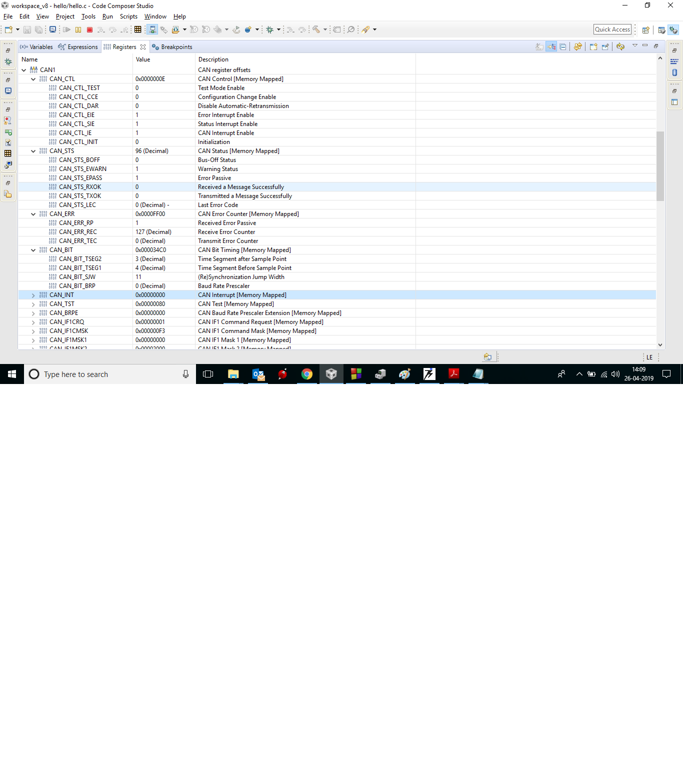
Error generated in Transmitter side
transmit registers
receive error