Part Number: TM4C123GH6PM
hello
i am working on two tm4c123gh6pm boards..My aim is to send data from one board to other using CAN protocol.
I have used Transceivers(MCP2551) and 120ohm terminations at both ends of the boards.
The Tx pin (PB5) of the Transmitter board is always high .There is no data coming out of the transmitter pin.
The Rx pin is at Low.
The registers are configured as follows after the code is build and debugged.
I have tired interpreting these registers and found that there is no bus-off state ,the interuppt counter is less than 256 which i think is fine.
Any help will be welcomed.
Thanks in advance.


Is the delay of 1 second used in the code is correct ?
The following is the code i have used at the Transmitter side.....
#include <stdbool.h>
#include <stdint.h>
#include "inc/hw_can.h"
#include "inc/hw_ints.h"
#include "inc/hw_memmap.h"
#include "driverlib/can.h"
#include "driverlib/gpio.h"
#include "driverlib/interrupt.h"
#include "driverlib/pin_map.h"
#include "driverlib/sysctl.h"
#include "driverlib/uart.h"
//#include "utils/uartstdio.h"
//*****************************************************************************
//
//! \addtogroup can_examples_list
//! <h1>Simple CAN TX (simple_tx)</h1>
//!
//! This example shows the basic setup of CAN in order to transmit messages
//! on the CAN bus. The CAN peripheral is configured to transmit messages
//! with a specific CAN ID. A message is then transmitted once per second,
//! using a simple delay loop for timing. The message that is sent is a 4
//! byte message that contains an incrementing pattern. A CAN interrupt
//! handler is used to confirm message transmission and count the number of
//! messages that have been sent.
//!
//! This example uses the following peripherals and I/O signals. You must
//! review these and change as needed for your own board:
//! - CAN0 peripheral
//! - GPIO Port B peripheral (for CAN0 pins)
//! - CAN0RX - PB4
//! - CAN0TX - PB5
//!
//! //!
//! This example uses the following interrupt handlers. To use this example
//! in your own application you must add these interrupt handlers to your
//! vector table.
//! - INT_CAN0 - CANIntHandler
//
//*****************************************************************************
//*****************************************************************************
//
// A counter that keeps track of the number of times the TX interrupt has
// occurred, which should match the number of TX messages that were sent.
//
//*****************************************************************************
volatile uint32_t g_ui32MsgCount = 0;
//*****************************************************************************
//
// A flag to indicate that some transmission error occurred.
//
//*****************************************************************************
volatile bool g_bErrFlag = 0;
//*****************************************************************************
void
SimpleDelay(void)
{
//
// Delay cycles for 1 second
//
SysCtlDelay(16000000 / 3);
}
//*****************************************************************************
//
// This function is the interrupt handler for the CAN peripheral. It checks
// for the cause of the interrupt, and maintains a count of all messages that
// have been transmitted.
//
//*****************************************************************************
void
CANIntHandler(void)
{
uint32_t ui32Status;
//
// Read the CAN interrupt status to find the cause of the interrupt
//
ui32Status = CANIntStatus(CAN0_BASE, CAN_INT_STS_CAUSE);
//
// If the cause is a controller status interrupt, then get the status
//
if(ui32Status == CAN_INT_INTID_STATUS)
{
//
// Read the controller status. This will return a field of status
// error bits that can indicate various errors. Error processing
// is not done in this example for simplicity. Refer to the
// API documentation for details about the error status bits.
// The act of reading this status will clear the interrupt. If the
// CAN peripheral is not connected to a CAN bus with other CAN devices
// present, then errors will occur and will be indicated in the
// controller status.
//
ui32Status = CANStatusGet(CAN0_BASE, CAN_STS_CONTROL);
//
// Set a flag to indicate some errors may have occurred.
//
g_bErrFlag = 1;
}
//
// Check if the cause is message object 1, which what we are using for
// sending messages.
//
else if(ui32Status == 1)
{
//
// Getting to this point means that the TX interrupt occurred on
// message object 1, and the message TX is complete. Clear the
// message object interrupt.
//
CANIntClear(CAN0_BASE, 1);
//
// Increment a counter to keep track of how many messages have been
// sent. In a real application this could be used to set flags to
// indicate when a message is sent.
//
g_ui32MsgCount++;
//
// Since the message was sent, clear any error flags.
//
g_bErrFlag = 0;
}
//
// Otherwise, something unexpected caused the interrupt. This should
// never happen.
//
else
{
//
// Spurious interrupt handling can go here.
//
}
}
//*****************************************************************************
//
// Configure the CAN and enter a loop to transmit periodic CAN messages.
//
//*****************************************************************************
//#define CAN_STATUS_BUS_OFF
int
main(void)
{
#if defined(TARGET_IS_TM4C129_RA0) || \
defined(TARGET_IS_TM4C129_RA1) || \
defined(TARGET_IS_TM4C129_RA2)
uint32_t ui32SysClock;
#endif
//***************************************
tCANMsgObject sCANMessage;
uint8_t ui32MsgData;
uint8_t *pui8MsgData;
pui8MsgData = (uint8_t *)&ui32MsgData;
//*************************************************
tCANBitClkParms cantiming;
//
// Set the clocking to run directly from the external crystal/oscillator.
// TODO: The SYSCTL_XTAL_ value must be changed to match the value of the
// crystal on your board.
//
#if defined(TARGET_IS_TM4C129_RA0) || \
defined(TARGET_IS_TM4C129_RA1) || \
defined(TARGET_IS_TM4C129_RA2)
ui32SysClock = SysCtlClockFreqSet((SYSCTL_XTAL_25MHZ |
SYSCTL_OSC_MAIN |
SYSCTL_USE_OSC)
25000000);
#else
SysCtlClockSet(SYSCTL_SYSDIV_1 | SYSCTL_USE_OSC | SYSCTL_OSC_MAIN |
SYSCTL_XTAL_25MHZ);
#endif
//
// Set up the serial console to use for displaying messages. This is
// just for this example program and is not needed for CAN operation.
//
//InitConsole();
//
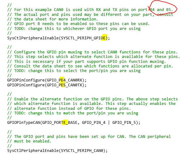
// For this example CAN0 is used with RX and TX pins on port B4 and B5.
// The actual port and pins used may be different on your part, consult
// the data sheet for more information.
// GPIO port B needs to be enabled so these pins can be used.
// TODO: change this to whichever GPIO port you are using
//
SysCtlPeripheralEnable(SYSCTL_PERIPH_GPIOE);
//
// Configure the GPIO pin muxing to select CAN0 functions for these pins.
// This step selects which alternate function is available for these pins.
// This is necessary if your part supports GPIO pin function muxing.
// Consult the data sheet to see which functions are allocated per pin.
// TODO: change this to select the port/pin you are using
//
GPIOPinConfigure(GPIO_PE4_CAN0RX);
GPIOPinConfigure(GPIO_PE5_CAN0TX);
//
// Enable the alternate function on the GPIO pins. The above step selects
// which alternate function is available. This step actually enables the
// alternate function instead of GPIO for these pins.
// TODO: change this to match the port/pin you are using
//
GPIOPinTypeCAN(GPIO_PORTE_BASE, GPIO_PIN_4 | GPIO_PIN_5);
//
// The GPIO port and pins have been set up for CAN. The CAN peripheral
// must be enabled.
//
SysCtlPeripheralEnable(SYSCTL_PERIPH_CAN0);
//
// Initialize the CAN controller
//
CANInit(CAN0_BASE);
CANBitTimingSet(CAN0_BASE, &cantiming);
//
// Set up the bit rate for the CAN bus. This function sets up the CAN
// bus timing for a nominal configuration. You can achieve more control
// over the CAN bus timing by using the function CANBitTimingSet() instead
// of this one, if needed.
// In this example, the CAN bus is set to 500 kHz. In the function below,
// the call to SysCtlClockGet() or ui32SysClock is used to determine the
// clock rate that is used for clocking the CAN peripheral. This can be
// replaced with a fixed value if you know the value of the system clock,
// saving the extra function call. For some parts, the CAN peripheral is
// clocked by a fixed 8 MHz regardless of the system clock in which case
// the call to SysCtlClockGet() or ui32SysClock should be replaced with
// 8000000. Consult the data sheet for more information about CAN
// peripheral clocking.
//
#if defined(TARGET_IS_TM4C129_RA0) || \
defined(TARGET_IS_TM4C129_RA1) || \
defined(TARGET_IS_TM4C129_RA2)
CANBitRateSet(CAN0_BASE, ui32SysClock, 1000000);
#else
CANBitRateSet(CAN0_BASE, SysCtlClockGet(), 1000000);
#endif
//
// Enable interrupts on the CAN peripheral. This example uses static
// allocation of interrupt handlers which means the name of the handler
// is in the vector table of startup code. If you want to use dynamic
// allocation of the vector table, then you must also call CANIntRegister()
// here.
//
// CANIntRegister(CAN0_BASE, CANIntHandler); // if using dynamic vectors
//
CANIntEnable(CAN0_BASE, CAN_INT_MASTER | CAN_INT_ERROR | CAN_INT_STATUS);
//
// Enable the CAN interrupt on the processor (NVIC).
//
IntEnable(INT_CAN0);
//
// Enable the CAN for operation.
//
CANEnable(CAN0_BASE);
///////////////////////////////////////////
//**************************************************
/////////////////////////////////////////////////////////////////
// Initialize the message object that will be used for sending CAN
// messages. The message will be 4 bytes that will contain an incrementing
// value. Initially it will be set to 0.
//
ui32MsgData = 0;
sCANMessage.ui32MsgID = 0;
sCANMessage.ui32MsgIDMask = 0;
sCANMessage.ui32Flags = MSG_OBJ_TX_INT_ENABLE;
sCANMessage.ui32MsgLen = sizeof(pui8MsgData);
sCANMessage.pui8MsgData = pui8MsgData;
cantiming.ui32SyncPropPhase1Seg=3;
cantiming.ui32Phase2Seg=1;
cantiming.ui32SJW=1;
cantiming.ui32QuantumPrescaler=5;
//
// Enter loop to send messages. A new message will be sent once per
// second. The 4 bytes of message content will be treated as an uint32_t
// and incremented by one each time.
//
while(1)
{
//
// Print a message to the console showing the message count and the
// contents of the message being sent.
//UARTprintf("Sending msg: 0x%02X %02X %02X %02X",
// pui8MsgData[0], pui8MsgData[1], pui8MsgData[2],
// pui8MsgData[3]);
// Send the CAN message using object number 1 (not the same thing as
// CAN ID, which is also 1 in this example). This function will cause
// the message to be transmitted right away.
//
CANMessageSet(CAN0_BASE, 1, &sCANMessage, MSG_OBJ_TYPE_TX);
//
// Now wait 1 second before continuing
//
SimpleDelay();
// Check the error flag to see if errors occurred
//
if(g_bErrFlag)
{
// UARTprintf(" error - cable connected?\n");
}
else
{
//
// If no errors then print the count of message sent
//
// UARTprintf(" total count = %u\n", g_ui32MsgCount);
}
//
// Increment the value in the message data.
//
ui32MsgData++;
}
//
// Return no errors
//
return (0);
}