This thread has been locked.

If you have a related question, please click the "Ask a related question" button in the top right corner. The newly created question will be automatically linked to this question.

EK-TM4C123GXL: UART receives part of the message, with or without FIFO

Part Number: EK-TM4C123GXL
Other Parts Discussed in Thread: PGA460

Hi,

I was looking for answers for this issue but they did not seem to help, therefore will put my own question.

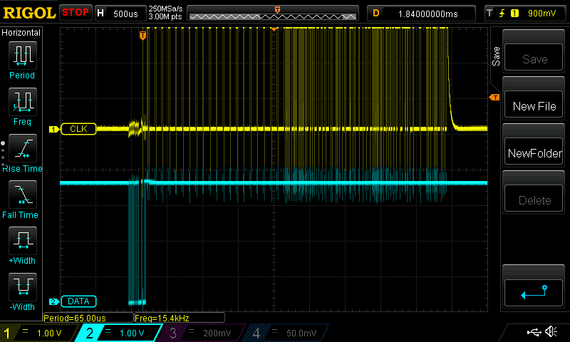
I am working with Tiva C series TM4C123GXL and PGA460 ultrasound sensor, firstly I am just trying to receive some initial messages in order to continue. However, I have encountered an issue that longer messages do not come in full. I tried with FIFO of different sizes and without it, all come to same issue that the message received is incomplete, although looking at oscilloscope, the message does arrive in full (see image bellow). Without FIFO I get 6 bytes of data plus one byte that should not appear when interrupt happens. The very first byte in the RX that is stored is not related to the received message as all messages start with 0x40 but first byte "received" is always 0x00 and second one is 0x40, so I am not sure how to fix this issue either. With FIFO I am not getting whole message either, the amount depends on size for FIFO. I am trying to receive in this case 45 bytes (in general message is not constant size but this one is one of the largest). The code I am using is bellow (adapted from uart_echo.c example, which works).  Interrupt is set up in the startup file accordingly.

#include "Additional_libraries/all_includes.h"

uint8_t test[3] = {0x55, 0x0B, 0xF4};
uint8_t t[45];
int i =0;

void GPIOPinUnlockGPIO(uint32_t ui32Port, uint8_t ui8Pins) {
    HWREG(ui32Port + GPIO_O_LOCK) = GPIO_LOCK_KEY;      // Unlock the port
    HWREG(ui32Port + GPIO_O_CR) |= ui8Pins;             // Unlock the Pin
    HWREG(ui32Port + GPIO_O_LOCK) = 0;                  // Lock the port
}


void UART2IntHandler(void)
{
    uint32_t ui32Status;

    //
    // Get the interrrupt status.
    //
    ui32Status = UARTIntStatus(UART2_BASE, true);

    //
    // Clear the asserted interrupts.
    //
    UARTIntClear(UART2_BASE, ui32Status);

    //
    // Loop while there are characters in the receive FIFO.
    //
    if(ui32Status & UART_INT_RX)
    {
    while(UARTCharsAvail(UART2_BASE) && i!=45)
    {
        //
        // Read the next character from the UART and write it back to the UART.
        //
        t[i] = UARTCharGetNonBlocking(UART2_BASE);

        SysCtlDelay(SysCtlClockGet() / (1000 * 3));

        i++;
    }
    if(i==45)
    {
        i=0;
    }
    }
}

//*****************************************************************************
//
// Send a string to the UART.
//
//*****************************************************************************
void UARTSend(const uint8_t *pui8Buffer, uint32_t ui32Count)
{
    //
    // Loop while there are more characters to send.
    //
    while(ui32Count--)
    {
        //
        // Write the next character to the UART.
        //
        ROM_UARTCharPut(UART2_BASE, *pui8Buffer++);
    }
}

//*****************************************************************************
//
// This example demonstrates how to send a string of data to the UART.
//
//*****************************************************************************
int main(void)
{
    //
    // Set the clocking to run directly from the crystal.
    //
    ROM_SysCtlClockSet(SYSCTL_SYSDIV_1 | SYSCTL_USE_OSC | SYSCTL_OSC_MAIN |
                       SYSCTL_XTAL_16MHZ);
    //
    // Enable the peripherals used by this example.
    //
    SysCtlPeripheralReset(SYSCTL_PERIPH_UART2);
    SysCtlPeripheralReset(SYSCTL_PERIPH_GPIOD);
    ROM_SysCtlPeripheralEnable(SYSCTL_PERIPH_UART2);
    ROM_SysCtlPeripheralEnable(SYSCTL_PERIPH_GPIOD);

    SysCtlDelay(10);

    GPIOPinUnlockGPIO(GPIO_PORTD_BASE, GPIO_PIN_7);

    //
    // Enable processor interrupts.
    //
    ROM_IntMasterEnable();

    //
    // Set GPIO A0 and A1 as UART pins.
    //
    GPIOPinConfigure(GPIO_PD6_U2RX);
    GPIOPinConfigure(GPIO_PD7_U2TX);
    ROM_GPIOPinTypeUART(GPIO_PORTD_BASE, GPIO_PIN_6 | GPIO_PIN_7);
    SysCtlDelay(10);
    //
    // Configure the UART for 115,200, 8-N-1 operation.
    //
    ROM_UARTConfigSetExpClk(UART2_BASE, ROM_SysCtlClockGet(), 115200,
                            (UART_CONFIG_WLEN_8 | UART_CONFIG_STOP_TWO |
                             UART_CONFIG_PAR_NONE));
    SysCtlDelay(10);
    //
    // Enable the UART interrupt.
    //
    UARTFIFOEnable(UART2_BASE);
    //UARTFIFOLevelSet(UART2_BASE,UART_FIFO_TX4_8, UART_FIFO_RX4_8);
    SysCtlDelay(10);
    UARTIntEnable(UART2_BASE, UART_INT_RX);
    UARTIntDisable(UART2_BASE, UART_INT_TX);

    UARTEnable(UART2_BASE);
    UARTFIFODisable(UART2_BASE);
    ROM_IntEnable(INT_UART2);
    //
    // Prompt for text to be entered.
    //


    //
    // Loop forever echoing data through the UART.
    //
    while(1)
    {
        UARTSend(test,sizeof(test));
        SysCtlDelay(1000000);
    }
}

  • Hi,

      In your scope, what is the yellow and what is the cyan? It says clock and data. The UART is asynchronous. It has not have clock. Unless you meant the clock for RX and data for TX.   

     I have some doubt with your code below. When there is no more data received in the UART then it will break out of the loop. For example, you only receive 6 bytes and the ISR will be exited and the the variable "i" is reset to 0. Next time when you receive the next interrupt, let's suppose the 7th byte has arrived, it will start the "i" with 0 again and overwrite the previous 6 bytes just received. I think this is the problem. 

    if(ui32Status & UART_INT_RX)
        {
        while(UARTCharsAvail(UART2_BASE) && i!=45)
        {
            //
            // Read the next character from the UART and write it back to the UART.
            //
            t[i] = UARTCharGetNonBlocking(UART2_BASE);
    
            SysCtlDelay(SysCtlClockGet() / (1000 * 3));
    
            i++;
        }
        if(i==45)
        {
            i=0;
        }
        }

  • Hi,
    Thank you for your response. I didn't think that the picture may mislead here. In the oscilloscope, the names are default ones, they have nothing to do with CLK or DATA. The blue line is the transmission from TIVa to the sensor, yellow one is the response. It is supposed to receive 45 bytes and stops after 6 bytes read and continues to poppulate the array with exact same values, that is my question why it does that. I have managed to fix that issue as it was the delay I kept from the example which I removed from the interrupt handler and it fixed that issue - it reads whole message. However it still adds a zero to first position of the array and only after that the response from the message. That is the only issue left to resolve. I do know that with other MCUs I have usued I didn't have this 0x00 byte added when interrupt is triggered and it is not part of the message, it just seems that the Tiva adds it by itself.
  • Hi Edvardas,
    Glad that you are making good progress.

    Can you try to call UARTCharsAvail() in the main() function before your while loop to make sure there is no residual data in the Rx FIFO. If there is any residual data already existing then read them and discard them until there is no more residual data?
  • I did check that and it does return 0 before sending the message to the sensor, after finishing reading the buffer, it it does add a 0x00 as first byte. However, it doesnt happen everytime, closer to 2/3 and the other time it would come in correct form. Can this be related to clock speeds? Right now I am testing at 40MHz.
  • Hi,
    In your original code you were using the OSC as the source clock and it is running only 16MHz. Have you change the clock setting since then?
    ROM_SysCtlClockSet(SYSCTL_SYSDIV_1 | SYSCTL_USE_OSC | SYSCTL_OSC_MAIN |
    SYSCTL_XTAL_16MHZ);

    Do you see any error flags in the UARTRSR register? I don't think it is related to the clock speed but you can try with different frequency and will you see any difference?

    Please also note that the UART is a full-duplex device. While you are transmitting the command sequence {0x55, 0x0B, 0xF4} on the TX it is also receiving data on the RX at the same time. You need to make sure during this 3-byte command transmission, whatever is received (i.e. 0) is ignored if your valid data only comes after the 3-byte command.
  • Yeah I did notice that it transmits and receives at the same time, wasn't aware it is full-duplex. I had delays before just as safety option but now I will add them so I wouldn't confuse the sensor. Also, increasing clock speed to 50MHz removed the 0x00 in the reading buffer. Thank you for your help!