Part Number: TM4C1294NCPDT
Other Parts Discussed in Thread: EK-TM4C1294XL
I tried to transmit ADC information from one TIVAC to another TIVAC through CAN bus. I attached the CAN Transmit code below. I cant able to transmit the information through CAN bus I got following errors plz help to to solve this
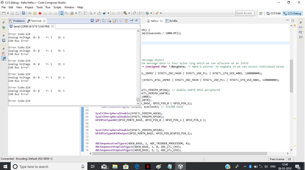
I am getting error code as 224 and shows CAN bus error even I tried to figure out through CRO but iam not getting any signal from CAN TX/RX pins PB0 and PB1

Here the CAN STS TXOK is still zero I dobubt whether my CAN controller is working or not
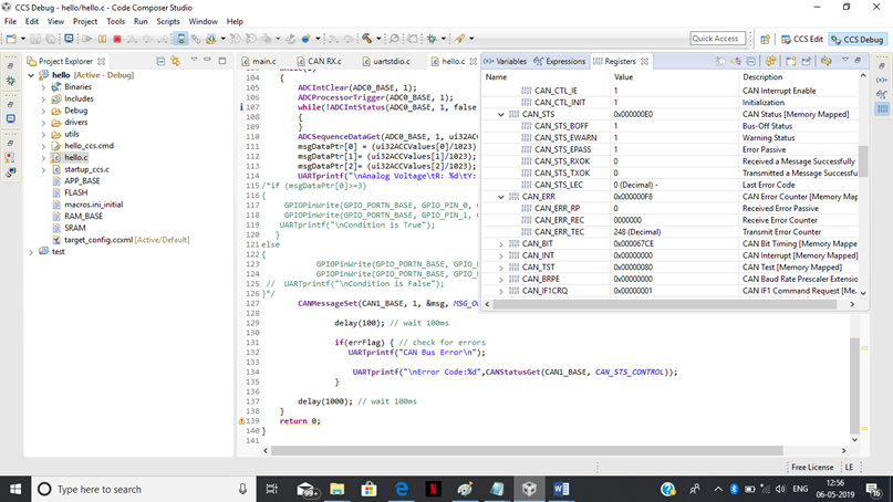
Here the CAN ERR TEC register shows 224 as code what does it mean clarify
CAN TX Code
#include <stdint.h>
#include <stdbool.h>
#include "inc/hw_memmap.h"
#include "inc/hw_types.h"
#include "driverlib/debug.h"
#include "driverlib/sysctl.h"
#include "driverlib/gpio.h"
#include "driverlib/adc.h"
#include "inc/hw_memmap.h"
#include "driverlib/uart.h"
#include "driverlib/pin_map.h"
#include "utils/uartstdio.h"
#include "inc/hw_can.h"
#include "inc/hw_ints.h"
#include "driverlib/can.h"
#include "driverlib/interrupt.h"
#include "utils/uartstdio.h"
unsigned int sysClock;
volatile bool errFlag = 0; // transmission error flag
unsigned int sysClock; // clockspeed in hz
volatile int status;
volatile bool errflag;
void CANIntHandler(void) {
unsigned long status = CANIntStatus(CAN1_BASE, CAN_INT_STS_CAUSE); // read interrupt status
if(status == CAN_INT_INTID_STATUS) { // controller status interrupt
status = CANStatusGet(CAN1_BASE, CAN_STS_CONTROL); // read back error bits, do something with them?
errFlag = 1;
} else if(status == 1) { // message object 1
CANIntClear(CAN1_BASE, 1); // clear interrupt
errFlag = 0; // clear any error flags
} else { // should never happen
UARTprintf("Unexpected CAN bus interrupt\n");
}
}
void delay(unsigned int milliseconds) {
SysCtlDelay((sysClock / 3) * (milliseconds / 1000.0f));
}
int main(void)
{
uint32_t ui32ACCValues[4];
volatile uint32_t ui32AccX;
volatile uint32_t ui32AccY;
volatile uint32_t ui32AccZ;
tCANMsgObject msg; // the CAN message object
unsigned int msgData; // the message data is four bytes long which we can allocate as an int32
unsigned char *msgDataPtr = (unsigned char *)&msgData; // make a pointer to msgData so we can access individual bytes
SysCtlClockFreqSet((SYSCTL_XTAL_25MHZ | SYSCTL_OSC_MAIN | SYSCTL_USE_PLL | SYSCTL_CFG_VCO_480), 120000000);
sysClock = SysCtlClockFreqSet((SYSCTL_XTAL_25MHZ | SYSCTL_OSC_MAIN | SYSCTL_USE_PLL | SYSCTL_CFG_VCO_480), 120000000);
// Set up debugging UART
SysCtlPeripheralEnable(SYSCTL_PERIPH_GPIOA); // enable UART0 GPIO peripheral
SysCtlPeripheralEnable(SYSCTL_PERIPH_UART0);
GPIOPinConfigure(GPIO_PA0_U0RX);
GPIOPinConfigure(GPIO_PA1_U0TX);
GPIOPinTypeUART(GPIO_PORTA_BASE, GPIO_PIN_0 | GPIO_PIN_1);
UARTStdioConfig(0, 115200, sysClock); // 115200 baud
SysCtlPeripheralEnable(SYSCTL_PERIPH_ADC0);
SysCtlPeripheralEnable(SYSCTL_PERIPH_GPIOE);
GPIOPinTypeADC(GPIO_PORTE_BASE, GPIO_PIN_0 | GPIO_PIN_1 | GPIO_PIN_2 );
SysCtlPeripheralEnable(SYSCTL_PERIPH_GPION);
GPIOPinTypeGPIOOutput(GPIO_PORTN_BASE, GPIO_PIN_0|GPIO_PIN_1);
ADCSequenceConfigure(ADC0_BASE, 1, ADC_TRIGGER_PROCESSOR, 0);
ADCSequenceStepConfigure(ADC0_BASE, 1, 0, ADC_CTL_CH3);
ADCSequenceStepConfigure(ADC0_BASE, 1, 1, ADC_CTL_CH2);
ADCSequenceStepConfigure(ADC0_BASE, 1, 2, ADC_CTL_CH1|ADC_CTL_IE|ADC_CTL_END);
ADCSequenceEnable(ADC0_BASE, 1);
SysCtlPeripheralEnable(SYSCTL_PERIPH_GPIOB); // enable CAN1 GPIO peripheral
GPIOPinConfigure(GPIO_PB0_CAN1RX);
GPIOPinConfigure(GPIO_PB1_CAN1TX);
GPIOPinTypeCAN(GPIO_PORTB_BASE, GPIO_PIN_0 | GPIO_PIN_1);
SysCtlPeripheralEnable(SYSCTL_PERIPH_CAN1);
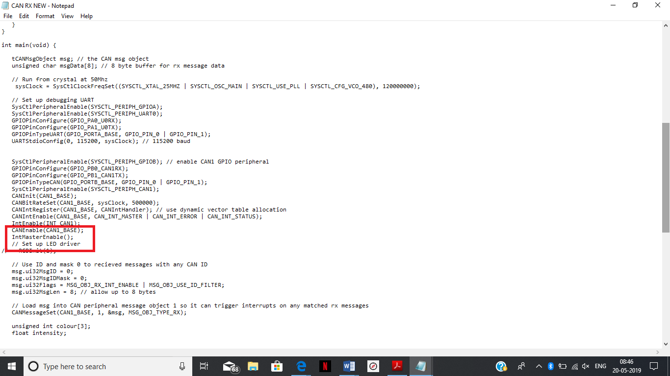
CANInit(CAN1_BASE);
CANBitRateSet(CAN1_BASE, sysClock, 500000);
CANIntRegister(CAN1_BASE, CANIntHandler); // use dynamic vector table allocation
CANIntEnable(CAN1_BASE, CAN_INT_MASTER | CAN_INT_ERROR | CAN_INT_STATUS);
CANIntClear(CAN1_BASE,CAN_INT_STATUS);
IntEnable(INT_CAN1);
CANEnable(CAN1_BASE);
// Set up msg object
msgData = 0;
msg.ui32MsgID = 1;
msg.ui32MsgIDMask = 0;
msg.ui32Flags = MSG_OBJ_TX_INT_ENABLE;
msg.ui32MsgLen = sizeof(msgDataPtr);
msg.pui8MsgData = msgDataPtr;
while(1)
{
ADCIntClear(ADC0_BASE, 1);
ADCProcessorTrigger(ADC0_BASE, 1);
while(!ADCIntStatus(ADC0_BASE, 1, false))
{
}
ADCSequenceDataGet(ADC0_BASE, 1, ui32ACCValues);
msgDataPtr[0] = (ui32ACCValues[0]/1023);
msgDataPtr[1]= (ui32ACCValues[1]/1023);
msgDataPtr[2]= (ui32ACCValues[2]/1023);
UARTprintf("\nAnalog Voltage\tR: %d\tY: %d\tB: %d\n",msgDataPtr[0],msgDataPtr[1],msgDataPtr[2]); // write colour to UART for debugging
/*if (msgDataPtr[0]>=3)
{
GPIOPinWrite(GPIO_PORTN_BASE, GPIO_PIN_0, GPIO_PIN_0);
GPIOPinWrite(GPIO_PORTN_BASE, GPIO_PIN_1, 0x0);
UARTprintf("\nCondition is True");
}
else
{
GPIOPinWrite(GPIO_PORTN_BASE, GPIO_PIN_1,GPIO_PIN_1 );
GPIOPinWrite(GPIO_PORTN_BASE, GPIO_PIN_0, 0x0);
// UARTprintf("\nCondition is False");
}*/
CANMessageSet(CAN1_BASE, 1, &msg, MSG_OBJ_TYPE_TX); // send as msg object 1
delay(100); // wait 100ms
if(errFlag) { // check for errors
UARTprintf("CAN Bus Error\n");
UARTprintf("\nError Code:%d",CANStatusGet(CAN1_BASE, CAN_STS_CONTROL));
}
delay(1000); // wait 100ms
}
return 0;
}
CAN Receive code
/*
* CAN bus LED controller slave firmware
* Written for TI Tiva TM4C123GH6PM
*/
#include <stdint.h>
#include <stdbool.h>
#include "inc/hw_memmap.h"
#include "inc/hw_types.h"
#include "driverlib/debug.h"
#include "driverlib/sysctl.h"
#include "driverlib/gpio.h"
#include "driverlib/adc.h"
#include "inc/hw_memmap.h"
#include "driverlib/uart.h"
#include "driverlib/pin_map.h"
#include "utils/uartstdio.h"
#include "inc/hw_can.h"
#include "inc/hw_ints.h"
#include "driverlib/can.h"
#include "driverlib/interrupt.h"
#include "utils/uartstdio.h"
volatile bool rxFlag = 0; // msg recieved flag
volatile bool errFlag = 0; // error flag
// CAN interrupt handler
void CANIntHandler(void) {
unsigned long status = CANIntStatus(CAN1_BASE, CAN_INT_STS_CAUSE); // read interrupt status
if(status == CAN_INT_INTID_STATUS) { // controller status interrupt
status = CANStatusGet(CAN1_BASE, CAN_STS_CONTROL);
errFlag = 1;
} else if(status == 1) { // msg object 1
CANIntClear(CAN1_BASE, 1); // clear interrupt
rxFlag = 1; // set rx flag
errFlag = 0; // clear any error flags
} else { // should never happen
UARTprintf("Unexpected CAN bus interrupt\n");
}
}
int main(void) {
tCANMsgObject msg; // the CAN msg object
unsigned char msgData[8]; // 8 byte buffer for rx message data
// Run from crystal at 50Mhz
SysCtlClockFreqSet((SYSCTL_XTAL_25MHZ | SYSCTL_OSC_MAIN | SYSCTL_USE_PLL | SYSCTL_CFG_VCO_480), 120000000);
// Set up debugging UART
SysCtlPeripheralEnable(SYSCTL_PERIPH_GPIOA);
SysCtlPeripheralEnable(SYSCTL_PERIPH_UART0);
GPIOPinConfigure(GPIO_PA0_U0RX);
GPIOPinConfigure(GPIO_PA1_U0TX);
GPIOPinTypeUART(GPIO_PORTA_BASE, GPIO_PIN_0 | GPIO_PIN_1);
UARTStdioConfig(0, 115200, 120000000);
SysCtlPeripheralEnable(SYSCTL_PERIPH_GPIOB); // enable CAN1 GPIO peripheral
GPIOPinConfigure(GPIO_PB0_CAN1RX);
GPIOPinConfigure(GPIO_PB1_CAN1TX);
GPIOPinTypeCAN(GPIO_PORTB_BASE, GPIO_PIN_0 | GPIO_PIN_1);
SysCtlPeripheralEnable(SYSCTL_PERIPH_CAN1);
CANInit(CAN1_BASE);
CANBitRateSet(CAN1_BASE, 120000000, 500000);
CANIntRegister(CAN1_BASE, CANIntHandler); // use dynamic vector table allocation
CANIntEnable(CAN1_BASE, CAN_INT_MASTER | CAN_INT_ERROR | CAN_INT_STATUS);
CANIntClear(CAN1_BASE,CAN_INT_STATUS);
IntEnable(INT_CAN1);
CANEnable(CAN1_BASE);
// Use ID and mask 0 to recieved messages with any CAN ID
msg.ui32MsgID = 0;
msg.ui32MsgIDMask = 0;
msg.ui32Flags = MSG_OBJ_RX_INT_ENABLE | MSG_OBJ_USE_ID_FILTER;
msg.ui32MsgLen = 8; // allow up to 8 bytes
// Load msg into CAN peripheral message object 1 so it can trigger interrupts on any matched rx messages
CANMessageSet(CAN1_BASE, 1, &msg, MSG_OBJ_TYPE_RX);
unsigned int colour[3];
float intensity;
while(1) {
if(rxFlag) { // rx interrupt has occured
msg.pui8MsgData = msgData; // set pointer to rx buffer
CANMessageGet(CAN1_BASE, 1, &msg, 0); // read CAN message object 1 from CAN peripheral
rxFlag = 0; // clear rx flag
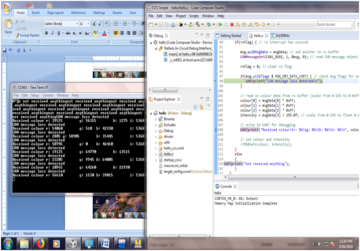
if(msg.ui32Flags & MSG_OBJ_DATA_LOST) { // check msg flags for any lost messages
UARTprintf("CAN message loss detected\n");
}
// read in colour data from rx buffer (scale from 0-255 to 0-0xFFFF for LED driver)
colour[0] = msgData[0] * 0xFF;
colour[1] = msgData[1] * 0xFF;
colour[2] = msgData[2] * 0xFF;
intensity = msgData[3] / 255.0f; // scale from 0-255 to float 0-1
// write to UART for debugging
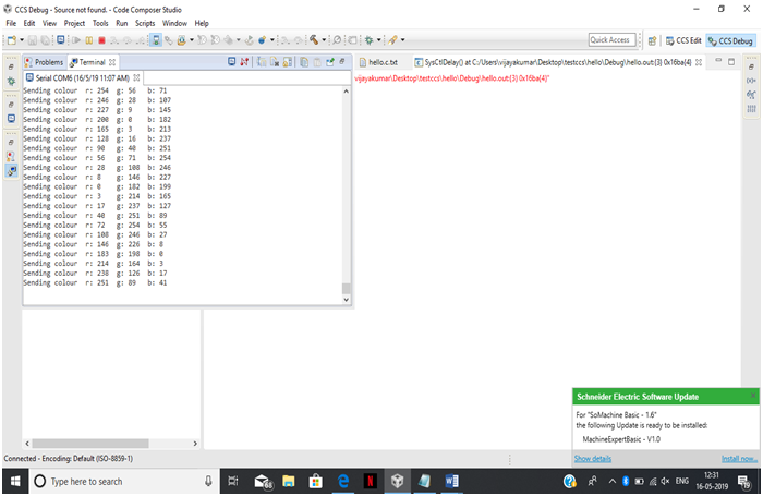
UARTprintf("Received colour\tr: %d\tg: %d\tb: %d\ti: %d\n", msgData[0], msgData[1], msgData[2], msgData[3]);
}}}
// set colour and intensity
//RGBSet(colour, intensity);
}
}
return 0;
}
iam not getting any information in receiver side the rxflag not getting any interrupt from transmitter side