This thread has been locked.

If you have a related question, please click the "Ask a related question" button in the top right corner. The newly created question will be automatically linked to this question.

TM4C123 and RS485

I am converting a standard UART interface into RS485. 

The flow of the program is presented in the flowchart below. The sensor is waiting for a command and when it is received, the sensor sends data continuosly utill a stop command is issued

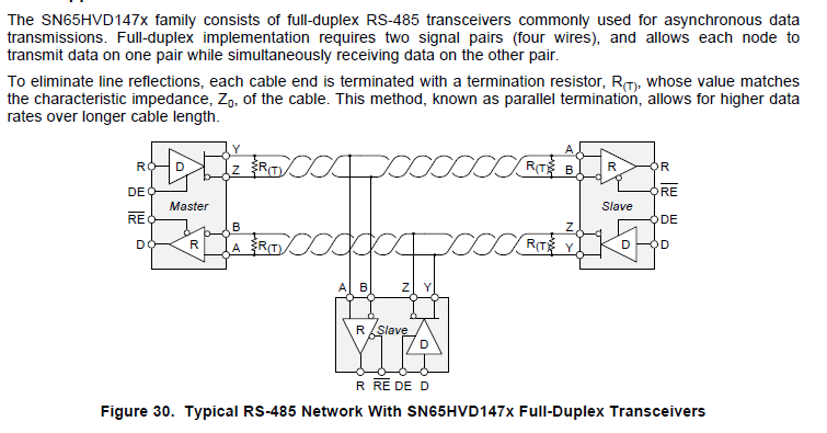
Both in the sensor and in the RS485 to USB interface the DE pin is connected to the RE pin of the tranceiver. In the sensor the two pins are connected to the CBUS2 pin of the chip FT232RL (this pin is configured as RXLED). In the sensor the two pins are connected to PORTF.3 of TM4C123 microcontroller.

The RS485 link I used in the test is few centimeters long and both the sensor and the interface have 120 Ohm termination resistors. ISL83485 is used as transceiver. Only in the interface the A pin is connected with a 560Ohm pull-up  resistor and the B pin with a 560 Ohm pull-down resistor.

The baudrate is 230400 but in the final configuration will be raised to 500k baud

Concerning the firmware side, I have made two tests

1) DE and RE* are low when the program starts. When the command is issued, DE and RE* are driven high at the beginning of the routine UARTSEND() and are driven low at the end of this routine. In this configuration the start command is issued correctly but  garbage data are received when sensor is transmitting. Another unexpected behaviour is that the stop command cannot be received correctly by the sensor

2) DE and RE* are low when the program starts. When the command is issued, DE and RE* are driven high at the beginning of the routine UARTSEND() and then are not driven low ath the end of the routine. In this configuration data are received correctly

I attach the most relevant part of the code for the communication point of view?

What I am missing? What is a suitable way of drive RS485 direction control signals for the firmware point of view?

Thanks in advance

void
UART1IntHandler(void)
{
    uint32_t ui32StatusRX;

    RingBufFlush(&rxRingBuf);
    //
    // Get the interrupt status.
    //
    ui32StatusRX = ROM_UARTIntStatus(UART1_BASE, true);

    //
    // Clear the asserted interrupts.
    //
    ROM_UARTIntClear(UART1_BASE, ui32StatusRX);
    // The receive timeout interrupt fires when you have received bytes in your FIFO but have not
    // gotten enough to fire your Rx interrupt. This is because the FIFO level select determines when that
    // T_RT)
    {
        // While there are bytes to read and there is space in the FIFO.
        while(UARTCharsAvail(UART1_BASE) && RingBufFull(&rxRingBuf) == false)
        {
            uint32_t ch = (uint8_t)ROM_UARTCharGet(UART1_BASE);
            // Write a byte straight from the hardware FIFO into our Rx FIFO for processing later.
            RingBufWriteOne(&rxRingBuf, ch);
        }
    }
    if((ui32StatusRX & UART_INT_RX) == UART_INT_RX)
    {
        //
        // Loop while there are characters in the receive FIFO.
        //
        while(ROM_UARTCharsAvail(UART1_BASE) && RingBufFull(&rxRingBuf) == false)
        {
            //
            // Read the next character from the UART
            //
            uint32_t ch = (uint8_t)ROM_UARTCharGet(UART1_BASE);
            RingBufWriteOne(&rxRingBuf,ch);
        }
    }
}

void
UARTSend(const uint8_t *pui8Buffer, uint32_t ui32Count)
{
 
    GPIO_PORTF_DATA_R |= TX_EN_RS485;
 
    while(ui32Count--)
    {
                ROM_UARTCharPut(UART1_BASE, *pui8Buffer++);
    }

  GPIO_PORTF_DATA_R &= ~ TX_EN_RS485;

}

void
ADXL357_SendAllAccData(void)
{
     char string[10];
    //collect data from sensor; the variable sample_in.z contains sensor data
     sprintf(string,"%+.6f",sample_in.z);
     UARTSend((uint8_t *)string,strlen(string));
    
     UARTSend("\n",1);
 
}

int
main(void){
    uint8_t ret = false;
    uint8_t acc_continuous_scan = 0x00;
    uint8_t module_continuous_scan = 0x00;
    ROM_IntMasterDisable();
    ConfigureMicroProcessor();
    LEDsTest();   
    ROM_IntMasterEnable();
    GPIO_PORTF_DATA_R &= ~ TX_EN_RS485;
          
    while(1)
    {
       
            if(RingBufEmpty(&rxRingBuf) == false)
            {
                // Did we receive enough bytes that it could be a message?
                if(RingBufUsed(&rxRingBuf) == sizeof(uint8_t[8]))
                {
                    uint8_t rec[8];
                    // Read the bytes into our received message structure.
                    RingBufRead(&rxRingBuf, (uint8_t*)&rec, sizeof(receivedMsg));
                    // Additional address
                    if (rec[2] == '0' && rec[3] == '1')
                    {
                        ADXL357_SendAllAccData();

                    }
               }
         }
        
   }
 }

  • I think you are switching the RS485 transceiver too soon. Just because the ROM_UARTCharPut() function has returned does not mean the serial transmission is complete. Use the function UARTBusy() to determine when all of the characters have finished transmitting.

    void
    UARTSend(const uint8_t *pui8Buffer, uint32_t ui32Count)
    {
        GPIO_PORTF_DATA_R |= TX_EN_RS485;
        while(ui32Count--)
        {
                    ROM_UARTCharPut(UART1_BASE, *pui8Buffer++);
        }
        while(ROM_UARTBusy(UART1_BASE))
        {
          // delay here until transmission is complete
        }
        GPIO_PORTF_DATA_R &= ~ TX_EN_RS485;
    }


  • Thanks for the reply. Now the transmission works also with the routine ADXL357_SendAllAccData(void).

    The only problem I face, is that when the sensor is trasmitting in continuous mode, I have to issue several times the related stop command.

    I have modified the code in the following way

    1) At the beginning of interrupt handler I have disabled the RS485 transmitter

    2) In both the routines  UARTSend and ADXL357_SendAllAccData I have used the instruction ROM_UARTCharsAvail(UART1_BASE)

    3) At the end of the routine UARTSend() I have put a small delay

    However, with these changes the issue in stop the trasnmission is still present


    void
    UART1IntHandler(void)
    {
        GPIO_PORTF_DATA_R &= ~ TX_EN_RS485;
        uint32_t ui32StatusRX;
    
        RingBufFlush(&rxRingBuf);
    
        //
        // Get the interrupt status.
        //
        ui32StatusRX = ROM_UARTIntStatus(UART1_BASE, true);
    
        //
        // Clear the asserted interrupts.
        //
        ROM_UARTIntClear(UART1_BASE, ui32StatusRX);
        // The receive timeout interrupt fires when you have received bytes in your FIFO but have not
        // gotten enough to fire your Rx interrupt. This is because the FIFO level select determines when that
        // T_RT)
        {
            // While there are bytes to read and there is space in the FIFO.
            while(UARTCharsAvail(UART1_BASE) && RingBufFull(&rxRingBuf) == false)
            {
                uint32_t ch = (uint8_t)ROM_UARTCharGet(UART1_BASE);
    
                            if(ch=='?')
                            {
                                
                               JumpToBootLoader();
                            }
                // Write a byte straight from the hardware FIFO into our Rx FIFO for processing later.
                RingBufWriteOne(&rxRingBuf, ch);
            }
        }
        if((ui32StatusRX & UART_INT_RX) == UART_INT_RX)
        {
            //
            // Loop while there are characters in the receive FIFO.
            //
            while(ROM_UARTCharsAvail(UART1_BASE) && RingBufFull(&rxRingBuf) == false)
            {
                //
                // Read the next character from the UART
                //
                uint32_t ch = (uint8_t)ROM_UARTCharGet(UART1_BASE);
                RingBufWriteOne(&rxRingBuf,ch);
            }
        }
    }
    
    void
    UARTSend(const uint8_t *pui8Buffer, uint32_t ui32Count)
    {
    
        if(!ROM_UARTCharsAvail(UART1_BASE))
        {
            GPIO_PORTF_DATA_R |= TX_EN_RS485;
             while(ui32Count--)
             {
                ROM_UARTCharPut(UART1_BASE, *pui8Buffer++);
             }
    
        }
       while(ROM_UARTBusy(UART1_BASE));   
        GPIO_PORTF_DATA_R &= ~ TX_EN_RS485;
        ROM_SysCtlDelay(200);
    
    }
    
    void
    ADXL357_SendAllAccData(void)
    {
         char string[10];
    
         sprintf(string,"%+.6f",sample_in.z);
         if(!ROM_UARTCharsAvail(UART1_BASE))
         {
         UARTSend((uint8_t *)string,strlen(string));
         UARTSend("\n",1);
          }

  • You need a higher level protocol to control the change of direction on the RS485 bus. Just changing the direction of the transceiver is not sufficient as the device which is continuously transmitting is still talking on the bus. The other option is to implement a 4-wire full duplex bus.
  • Here is a picture of a full duplex RS485 bus with one master and multiple slaves. There is no need to switch off the transceiver at the master. Each slave is then told when it can communicate (only one at a time) by commands from the master.