Because of the Thanksgiving holiday in the U.S., TI E2E™ design support forum responses may be delayed from November 25 through December 2. Thank you for your patience.

This thread has been locked.

If you have a related question, please click the "Ask a related question" button in the top right corner. The newly created question will be automatically linked to this question.

TM4C1294KCPDT: Vbat Pin short with Ground

Part Number: TM4C1294KCPDT

Dear,

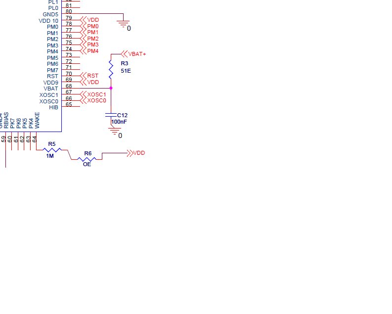
We are using TM4C1294KCPDT as our controller. To keep RTC running in power failuare we have connected battery cell on VBAT pin (Pin no 68) as shown in below figure.

Now issue is in some pieces RTC stop updating as power gets off. When we analyzed we found VBAT short with GND pin.

Could someone please guide us on the same?

Regards.

  • Hello Pallav,

    The image did not load right.

    Is this on a custom board? If so, have you looked for any possible soldering issues that could tie VBAT to ground? Is the ground connection seen both with battery inserted and no battery present? Have you verified the battery polarity is correct?

    Maybe the image will help me with additional ideas to look into.
  •  Hi Ralph,

    Sorry for image.

    Yes this is on custom board.

    No such way found in which VBAT could tie to ground.(Also system were working for some time and now it is not working).

    Yes, Shorting is with & without battery. But in one of the case we found that when battery is connected it shows shorting and when open there is no shorting. In the same device if we change battery it will start working as desired. Can you please suggest in which cases this can happen?

    Yes we have checked polarity is correct.

    Regards.

  • Hello Pallav,

    So to summarize and clarify a couple points:

    1) No potential ground connections were found when analyzing the PCB
    2) The failure occurs even without a battery present on the circuit, but not always.
    3) The failure may go away if using a new battery

    Have you checked the voltage for your battery and compared if the RC filter values implemented will avoid the Errata ELEC#02? www.ti.com/.../spmz850g.pdf

    What is the tolerance on those components?

    Is this occurring on a single board or multiple? And if only on a single board, how many functional boards are there?
  • Hello Pallav,

    I haven't heard back from you, have you been able to resolve this issue?

    If I don't hear back by end of the week, I will close this thread for now, but if you have not solved this issue then post a reply below (or open a new thread if the thread has locked due to time-out).
  • Dear Ralph,

    Sorry for late rely as i was not available. As you mentioned we have placed RC filter close enough to controller (Just 3.8mm away).

    Values as shown are 51E for resistor and 100nF for capacitor.

    As far as tolerance is concern for resister it is +/- 1% and for capacitor it is +/- 10%.

    Regards.

  • Hello Pallav,

    Regarding the values, I was asking for the battery voltage as the values depend on that as well since it's to control the ramp of the battery. If the battery has a specification regarding the ramp that could help too, or if you just measure the ramp of the voltage via an o-scope with the filter in place that could also indicate if the ramp is being kept slow enough or if its exceed the 0.7V/uSec limit.

    Also didn't see an answer for this question: Is this occurring on a single board or multiple? And if only on a single board, how many functional boards are there?

  • Dear Ralph,

    There are total 1k board. It has occured in 20 boards as of now.

    Related to waveform of battery i will get it for you in some time. Meanwhile battery voltage is 3V. And battery is CR2032.

    Reference link is as below.

    R

  • Hello Pallav,

    I spoke with another colleague about this and both of us believe that based on the symptoms and the scope of the failures, that this is related to ELEC#02 still.

    Can you do the following:

    1) Provide a scope shot of the VBAT ramp time with the RC filter in place on your custom board.

    2) Measure the current draw on a failing device vs a good device.

  • Sure. Will do it and update you in a days time.

    Regards.

  • Hello Pallav,

    Do you have any update on your observations of the requested tests?

  • Dear Ralph,

    We have observed that while controller is in hibernate then also it consumes 20mA from button cell just to run RTC.

    Regards.

  • Dear Ralph,

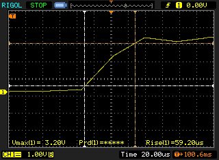
    Also as asked by you i checked with the battery ramp up voltage without filter it is 1.3V/us. But on controller pin after RC filter it is 0.7V/13us which is much slower than 0.7V/1us.

    Please find the screenshot of DSO for your reference.

    Regards.

  • Hello Pallav,

    20 mA makes it sound like the device is in Active mode. How are you determining the device has a short? Was it just due to the current measurement at VBAT?

    Have you done any continuity tests with the components removed to indicate that there is a short?

    Regarding the hibernation side, do you have any means to check if the device has been actived due to an unexpected wake event? Can you connect to the device to debug when it's in that state? Perhaps you can read the interrupt status register for the module?

  • Hello Pallav,

    Also, have you tried recovering the operation of any of these boards? If so, what steps have you taken along those lines?