This thread has been locked.

If you have a related question, please click the "Ask a related question" button in the top right corner. The newly created question will be automatically linked to this question.

CCS/TM4C129XNCZAD: 20 bit data transfer from microcontroller to DAC

Part Number: TM4C129XNCZAD

Tool/software: Code Composer Studio

dear all

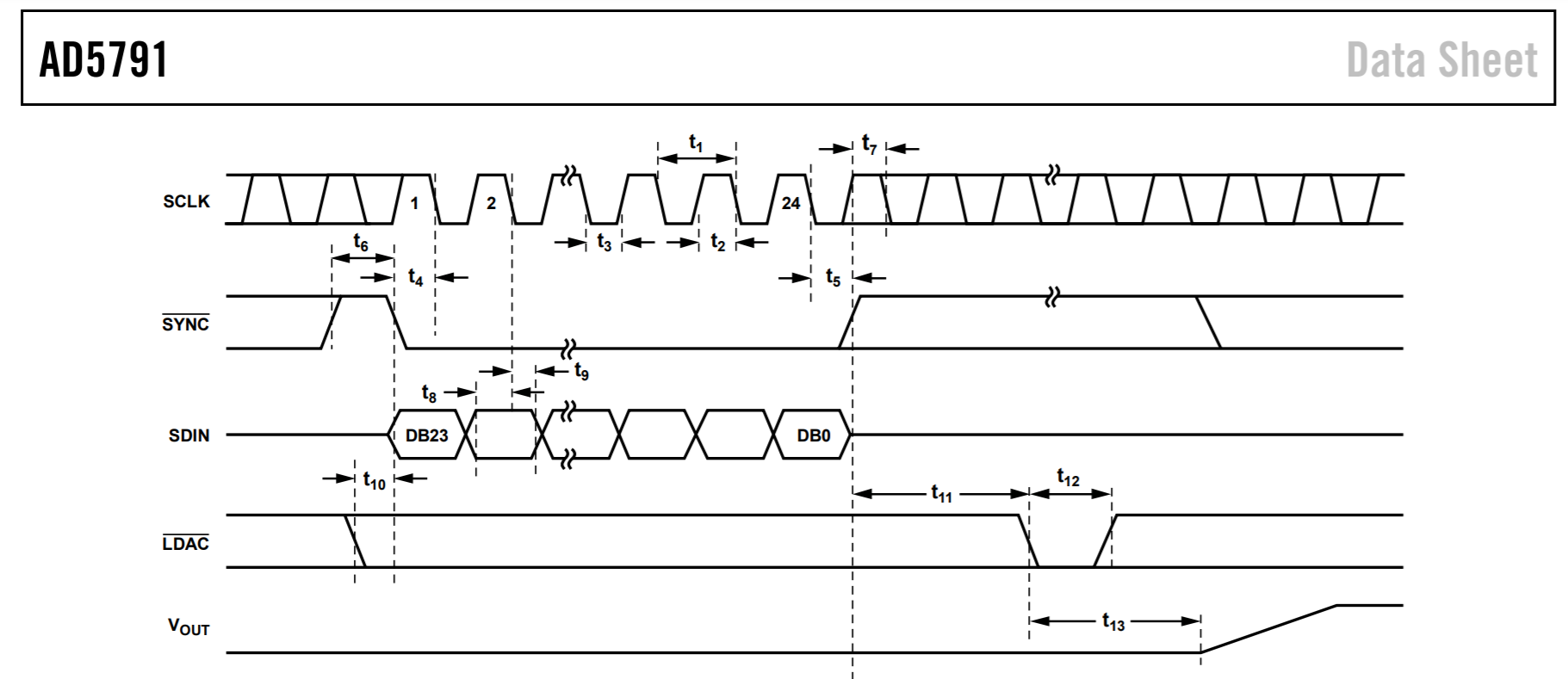
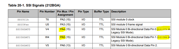
  can anybody suggest how to send 20 bit data to DAC ad5791 from microcontroller tm4c129xnczad . i saw in ssiconfigsetexpclk take only 4 to 16 bit data. please tell me how to do this

  • It looks to me like the AD5791 requires a 24 bit transfer.

    You can do this by manually toggling a GPIO pin low to start the SYNC and then do 3 8-bit transfers then set SYNC high. Or you could use the SSIAdvFrameHoldEnable() function to manipulate the FSS signal to do the SYNC function.

  • Dear all,

            i am using eval ad5791 board and trying to communicate with tm4c129x of texas instruemnts. i am sending data through serial interface(SSI) . but i am unable to get any output. i have checked that VDD=14V Vss=-14 , Vcc=3.3V iovcc=3.3 V , LDAC=0, RESET =1 clr=1 in which LDAC is parmanently shorted to gnd. .RESET is shorted iovcc. and clr is at logic 1 and i am

    sending data in 8 bit mode so i am sending in 3 cycle. in very first time i sent data 0x20012. and then 0x1fffff to get full output but iam unable to get any output. please help me to get output. i have attached the code

    #include "stdbool.h"
    #include "stdint.h"
    #include "gpio.h"
    #include "rom_map.h"
    #include "sysctl.h"
    #include "hw_memmap.h"
    #include "pin_map.h"
    #include "emac.h"
    #include "systick.h"
    #include "utils/ustdlib.h"
    #include "math.h"
    #include "driverlib/ssi.h"
    #include "tm4c129xnczad.h"
    #include "driverlib/rom.h"
    
    uint32_t pui32DataTx=0;
    uint32_t pui32DataTx1=0;
    uint32_t pui32DataTx2=0;
    uint32_t pui32DataTx3=0;
    
    void SSi_data(void);
    void dac_normal(void);
    void DAC_ldac(void);
    #define GPIO_PA2_SSI0CLK        0x0000080F
    #define GPIO_PA3_SSI0FSS        0x00000C0F
    #define  GPIO_PA4_SSI0RX      0x0000100F
    #define GPIO_PA5_SSI0TX      0x0000140F
    #define NUM_SSI_DATA            3
    #define SYS_TICK_DELAY 10000
    
    uint32_t ui32SysClock;
    
    void DAC_ldac()
        {
            MAP_SysCtlPeripheralEnable(SYSCTL_PERIPH_GPIOS);
            MAP_GPIOPinTypeGPIOOutput(GPIO_PORTS_BASE, GPIO_PIN_7); // sync pulse
            MAP_GPIOPinTypeGPIOOutput(GPIO_PORTS_BASE, GPIO_PIN_6);  //clr high
            MAP_GPIOPinWrite(GPIO_PORTS_BASE, GPIO_PIN_7, GPIO_PIN_7); //sync pulse high 
            MAP_GPIOPinWrite(GPIO_PORTS_BASE, GPIO_PIN_6, GPIO_PIN_6);
       
        }
    
    
    void dac_normal()
    {
        pui32DataTx = 0x200312;
        SSi_data();
       // pui32DataTx = 0x400002;
      //  SSi_data();
    
    }


    void SSi_data()
    {
    
     pui32DataTx1= pui32DataTx & 0x0000ff;
     pui32DataTx2= (pui32DataTx & 0x00ff00) >> 8;
     pui32DataTx3= (pui32DataTx & 0xff0000) >> 16;
     MAP_GPIOPinWrite(GPIO_PORTS_BASE, GPIO_PIN_7, 0);
    
     SSIDataPut(SSI0_BASE, pui32DataTx3);
     
                          MAP_GPIOPinWrite(GPIO_PORTS_BASE, GPIO_PIN_6, 0); //sync low
                         while(SSIBusy(SSI0_BASE))
                                {
                                }
     SSIDataPut(SSI0_BASE, pui32DataTx2);
    
                         while(SSIBusy(SSI0_BASE))
                                {
                                }
     SSIDataPut(SSI0_BASE, pui32DataTx1);
    
                         while(SSIBusy(SSI0_BASE))
                                {
                                }
    
    
                              SSIIntClear(SSI0_BASE,SSI_RXFF);
                              MAP_GPIOPinWrite(GPIO_PORTS_BASE, GPIO_PIN_7, GPIO_PIN_7); // Sync high


    }
    int main(void)
    {
    
            ui32SysClock = SysCtlClockFreqSet((SYSCTL_XTAL_25MHZ |SYSCTL_OSC_MAIN | SYSCTL_USE_PLL | SYSCTL_CFG_VCO_320),
            10000000);
            SysCtlPeripheralEnable(SYSCTL_PERIPH_SSI0);
            SysCtlPeripheralEnable(SYSCTL_PERIPH_GPIOA);
            SysCtlPeripheralEnable(SYSCTL_PERIPH_GPIOB);
            GPIOPinConfigure(GPIO_PA2_SSI0CLK);
            GPIOPinConfigure(GPIO_PA3_SSI0FSS);
            GPIOPinConfigure(GPIO_PA4_SSI0RX);
            GPIOPinConfigure(GPIO_PA5_SSI0TX);
            DAC_ldac();
            MAP_GPIOPinWrite(GPIO_PORTS_BASE, GPIO_PIN_7, GPIO_PIN_7);
            GPIOPinTypeSSI(GPIO_PORTA_BASE, GPIO_PIN_5 | GPIO_PIN_4 | GPIO_PIN_3 | GPIO_PIN_2);
            SSIConfigSetExpClk(SSI0_BASE, SysCtlClockGet(), SSI_FRF_MOTO_MODE_0,
                                   SSI_MODE_MASTER, 100000, 8);
            SSIEnable(SSI0_BASE);
            dac_normal();
    
    
            while(1)
            {
                              pui32DataTx = 0x1fffff;
                              SSi_data();
                              
            }
        //return 0;
    }

  • You have the TX and RX pins mislabeled. Do you have them wired correctly? PA4 is TX and PA5 is RX.

    Also, don't use SysCtlClockGet() function with the TM4C129x devices (line 102). That function is only for the TM4C123 devices. Use the variable ui32SysClock instead.

  • yes i have hardwired it correctly and i am observing at oscilloscope too but output is 0v on any input

  • thanks for your great help

    the problem sorted out