This thread has been locked.

If you have a related question, please click the "Ask a related question" button in the top right corner. The newly created question will be automatically linked to this question.

CCS/TM4C1290NCPDT: Where is GPIO_init located?

Part Number: TM4C1290NCPDT
Other Parts Discussed in Thread: SYSBIOS, TM4C1294NCPDT

Tool/software: Code Composer Studio

I started bringing up my board using the simple task project, which runs fine.  I'm now trying to start blinking an LED by cutting and pasting code from the usbserialdevice_DK_TM4C129X_TI example.  When linked the GPIO_init symbol is undefined.  I've looked through the USB code but cannot find the #include needed.  Code and linker data:

//----------------------------------------------------------------------------------------------------------------
//  main.cc
//
//  MAIN MAN !  Where all the Magic Starts.
//
//  Copyright (c) 2019 D.B. Associates.
//----------------------------------------------------------------------------------------------------------------


#include <stdint.h>
#include <stdbool.h>

#include "tm4c1290ncpdt.h"

#include <xdc/std.h>
#include <xdc/runtime/Error.h>
#include <xdc/runtime/System.h>

#include <ti/sysbios/BIOS.h>
#include <ti/sysbios/knl/Task.h>

#include <ti/drivers/GPIO.h>
#include <ti/drivers/gpio/GPIOTiva.h>

#include <driverlib/sysctl.h>
#include <driverlib/gpio.h>


/*
 *  ======== taskFxn ========
 */
Void taskFxn(UArg a0, UArg a1)
{
    System_printf("enter taskFxn()\n");

    Task_sleep(10);

    System_printf("exit taskFxn()\n");

    System_flush(); /* force SysMin output to console */
}


//---------------------
//  GENERAL CPU INIT  |
//----------------------------------------------------------------------------------------------------------------
void InitGeneral(void) {

    SysCtlPeripheralEnable(SYSCTL_PERIPH_GPIOA);
    SysCtlPeripheralEnable(SYSCTL_PERIPH_GPIOB);
    SysCtlPeripheralEnable(SYSCTL_PERIPH_GPIOC);
    SysCtlPeripheralEnable(SYSCTL_PERIPH_GPIOD);
    SysCtlPeripheralEnable(SYSCTL_PERIPH_GPIOE);
    SysCtlPeripheralEnable(SYSCTL_PERIPH_GPIOF);
    SysCtlPeripheralEnable(SYSCTL_PERIPH_GPIOG);
    SysCtlPeripheralEnable(SYSCTL_PERIPH_GPIOH);
    SysCtlPeripheralEnable(SYSCTL_PERIPH_GPIOJ);
    SysCtlPeripheralEnable(SYSCTL_PERIPH_GPIOK);
    SysCtlPeripheralEnable(SYSCTL_PERIPH_GPIOL);
    SysCtlPeripheralEnable(SYSCTL_PERIPH_GPIOM);
    SysCtlPeripheralEnable(SYSCTL_PERIPH_GPION);
    SysCtlPeripheralEnable(SYSCTL_PERIPH_GPIOP);
    SysCtlPeripheralEnable(SYSCTL_PERIPH_GPIOQ);
}
//----------------------------------------------------------------------------------------------------------------


//----------------------------------------------------------------------------------------------------------------
/*
 * Array of Pin configurations
 * NOTE: The order of the pin configurations must coincide with what was
 *       defined in DK_TM4C129X.h
 * NOTE: Pins not used for interrupts should be placed at the end of the
 *       array.  Callback entries can be omitted from callbacks array to
 *       reduce memory usage.
 */
GPIO_PinConfig gpioPinConfigs[] = {
    /* Input pins */
    /* DK_TM4C129X_BUTTON_SELECT */
//  GPIOTiva_PP_1 | GPIO_CFG_IN_PU | GPIO_CFG_IN_INT_RISING,
    /* DK_TM4C129X_BUTTON_UP */
//  GPIOTiva_PN_3 | GPIO_CFG_IN_PU | GPIO_CFG_IN_INT_RISING,
    /* DK_TM4C129X_BUTTON_DOWN */
//  GPIOTiva_PE_5 | GPIO_CFG_IN_PU | GPIO_CFG_IN_INT_RISING,

    // Output pins
    // LED D8
    GPIOTiva_PA_4 | GPIO_CFG_OUT_STD | GPIO_CFG_OUT_STR_HIGH | GPIO_CFG_OUT_LOW,

    // LED D9
    GPIOTiva_PA_5 | GPIO_CFG_OUT_STD | GPIO_CFG_OUT_STR_HIGH | GPIO_CFG_OUT_LOW,
};

/*
 * Array of callback function pointers
 * NOTE: The order of the pin configurations must coincide with what was
 *       defined in DK_TM4C129X.h
 * NOTE: Pins not used for interrupts can be omitted from callbacks array to
 *       reduce memory usage (if placed at end of gpioPinConfigs array).
 */
GPIO_CallbackFxn gpioCallbackFunctions[] = {
    NULL,  /* DK_TM4C129X_BUTTON_SELECT */
    NULL,  /* DK_TM4C129X_BUTTON_UP */
    NULL   /* DK_TM4C129X_BUTTON_DOWN */
};

/* The device-specific GPIO_config structure */
const GPIOTiva_Config GPIOTiva_config = {
    .pinConfigs = (GPIO_PinConfig *)gpioPinConfigs,
    .callbacks = (GPIO_CallbackFxn *)gpioCallbackFunctions,
    .numberOfPinConfigs = sizeof(gpioPinConfigs)/sizeof(GPIO_PinConfig),
    .numberOfCallbacks = sizeof(gpioCallbackFunctions)/sizeof(GPIO_CallbackFxn),
    .intPriority = (~0)
};
//----------------------------------------------------------------------------------------------------------------


//---------
//  MAIN  |
//----------------------------------------------------------------------------------------------------------------
Int main() {

    Task_Handle task;
    Error_Block eb;

    InitGeneral();
    GPIO_init();
//  InitGPIO();

    System_printf("enter main()\n");

    Error_init(&eb);
    task = Task_create(taskFxn, NULL, &eb);
    if (task == NULL) {
        System_printf("Task_create() failed!\n");
        BIOS_exit(0);
    }

    BIOS_start();    /* does not return */
    return(0);
}
//----------------------------------------------------------------------------------------------------------------

Thanks.

  • Hi Doug,

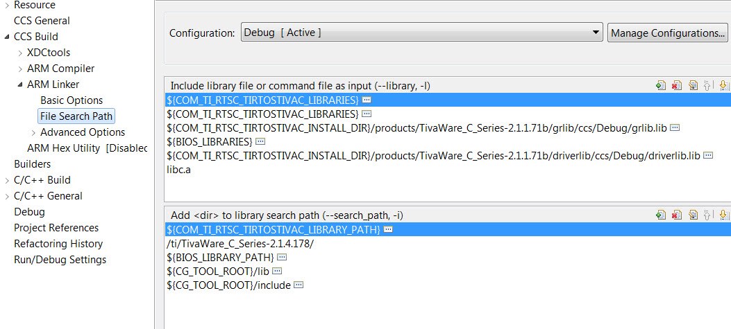
      Below is the linker searchpath that I see with the usbserialdevice_DK_TM4C129X_TI or any TI-RTOS examples for Tiva device. Yours look a bit different. I have no problem compiling after modifying the DK_TM4C129X.c like you did to configure the gpioPinConfigs structure and directly call the GPIO_init() in the main(). I'm not sure where you get the example from. Perhaps after mixing the TI-RTOS code/drivers/lib from different places, some hiccups happen.  I will suggest you start with a fresh example. Please import the GPIO Interrupt example from Resource Explorer and first compile it as is. Then you can modify the gpioPinConfigs[] the way you want it and see if you see any compilation problem. 

  • Thanks Charles.

    Yes, the gpiointerrupt_DK_TM4C129X_TI does compile and run on my DK_TM4C129X_TI, but that doesn't help me.  I was told I cannot, after a project has been created, change the CPU to the one I have (TM4C1290NCPDT).

    One difference I see between my project and the GPIO and USB example projects is that those projects were created with the Product TI-RTOS for TivaC while if I create my project as File->New->CCS Project  and under Projects and Templates SYS/BIOS->TI Target Examples->Typical, it is created with the Product SYS/BIOS 6.50.1.12;  if I change that in the project itself (unclick SYS/BIOS an click TI_RTOS then when I compile I get the error:

    error: xdc.cfg.Program: "C:/ti/ccs830/xdctools_3_51_01_18_core/packages/xdc/cfg/Program.xs", line 71: xdc.cfg.Program : The package 'ti.sysbios.knl' is not compatible with XDCtools used in this build. Please either use XDCtools compatible with that package, or update the product containing that package, or rebuild the package with XDCtools 3.50 or later.

    So how do I go about creating a TI-RTOS project for my CPU?

  • Hi Doug,

      I have not created a TIRTOS project like the way you did. I think the easiest way to create a TI-RTOS project is to use the Resource Explorer to download the empty project and build on it per your need. The empty project will have all the TI-RTOS drivers created for you. Please see below. I cannot comment on your building a new TI-RTOS project from CCS->New->CCS Project. If you want to follow that approach then i will have to pass your question to our TI-RTOS experts. 

    Here is the user's guide to getting started on TI-RTOS for TivaC. 

    http://www.ti.com/lit/ug/spruhu5d/spruhu5d.pdf

    Here is the link to all the workshops/training materials for TI-RTOS. You can watch the training videos. I will simply jump start with the TI_RTOS_Kernel_Workshop_Student_Guide_rev4.00.pdf. See below image.

  • Thanks Charles.

    I still don't think this helps me.  You say "open an empty project from Resource Explorer", I cannot find any "empty projects" in Resource Explorer, I only find projects for eval boards, and as I had been told in a prior post, I cannot change the CPU of a project once created.  Thanks for the links, already have them, and am working through the videos.  Why can't I just find out which library has GPIO_init?

    Help.

  • Hi Doug,

      Let me forward your post to our TI-RTOS experts on the best way to start a new TI-RTOS project for Tiva devices and your question about the library that contains the GPIO_init(). 


  • Doug,

    The best approach for using TI-RTOS libraries is to start with an existing TI-RTOS example project for one of the supported boards, following those instructions you’d seen in the getting started guide.  And then change project properties to indicate your specific device (under Properties General, in the Main tab select the device ID in the drop down for Variant, and then in the RTSC tab, change the device ID at the end of the Platform specification, for example: ti.platforms.tiva:TM4C1294NCPDT).  And then update the board files (e.g. EK_TM4C1294XL.c/h/cmd ) as needed for your board.  Depending on your board there may be several changes needed, but likely you can start by commenting out definitions that are not used by your app.  There used to be some detailed instructions for porting to a different device/board on a wiki page, I was going to send a link to that but see that the page is no longer active.  If you have issues doing this please reply back.

    I don’t know which other thread you were told you can’t change the device ID once you create a project. Was it for some other non-TI-RTOS software?  Can you post a link to that thread?

    To answer your question for the library that contains GPIO_init()… it is in the TI-RTOS install (for the 2.16.01.13 product) at: products/tidrivers_tivac_2_16_01_13/packages/ti/drivers/lib/drivers_tivaware.aem4f.  In a project you can navigate into Debug/configPkg and open linker.cmd to see the TI-RTOS libraries that get linked in.

    Regards,
    Scott

  • Re "Can't change the CPU of a project", I don't know how to link to that thread, and I don't know how to find the thread number, but here is a screen shot:

  • Doug,

    Thanks for the screen shot.  I searched and am not able to find that specific thread.  If you post the web link I should be able to find it.

    Have you been able to make any progress?

    Thanks,
    Scott

  •  

    Charles Tsai replied to CCS/TM4C1290NCPDT: Where is GPIO_init located?.

    I'm surprised that there isn't a thread number displayed that can be referenced.

    I took the usbserialdevice_DK_TM4C129X_TI, changed the device to my CPU.  It compiles but if I try to download it to my board I get the error:

    Unable to launch CCS debug-session based on current selection.

    The specified file

    "C:\ti\CCS_V8_Workspace\usbserialdevice_DK_TM4C129X_TI\NewTargetConfiguration.ccxml" does not exist in the file system.

    I had renamed the project to MVerse v2.0g, I don't know why it is referencing the other project.  This just happened so I haven't had a chance to go searching yet.

    Thanks for your help.

  • I updated the project with the JTAG interface and it created the .ccxml file and the programming gets further, now I'm getting "MVerse v2.0g.out:load failed".  I have previously successfully loaded and run a SYS/BIOS "Hello World" app that ran so I'll have to figure out what's going on now.

  • This is the error I'm getting:

    CORTEX_M4_0: GEL Output:
    Memory Map Initialization Complete
    CORTEX_M4_0: Trouble Writing Memory Block at 0x7ff0 on Page 0 of Length 0x24c0: Flash download failed! ...
    CORTEX_M4_0: File Loader: Verification failed: Target failed to write 0x00007FF0
    CORTEX_M4_0: GEL: File: C:\ti\Temp\MVerse v2.0f\Debug\MVerse v2.0g.out: Load failed.

  • I just confirmed that the "Typical SYS/BIOS Example" loads and runs correctly.

  • The Hello World app is smaller than the one I'm trying to load so this may be a faulty CPU chip.  Will get it replaced.

  • OK, turns out it was a defective CPU.  Now I'm off peeling the next layer of the onion.

    Thanks for your help.